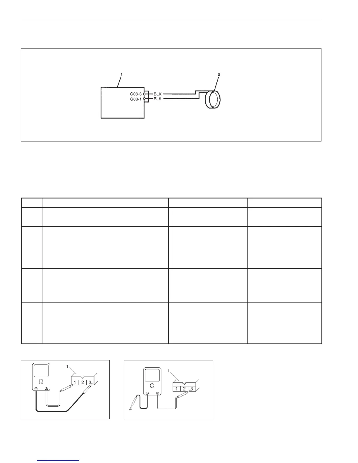
1. Immobilizer Control Module
2. Coil antenna
8G-12 IMMOBILIZER CONTROL SYSTEM (IF EQUIPPED)
1. Coil antenna coupler
1. Coil antenna coupler
Fig. 1 for Step 2 Fig. 2 for Step 3
DTC13 NO TRANSPONDER CODE TRANSMITTED FROM IGNITION KEY
DTC14 COIL ANTENNA CIRCUIT MALFUNCTION
DESCRIPTION:
Immobilizer Control Module energizes the coil antenna when the ignition switch is ON and reads Transponder code
from the ignition key. When Immobilizer Control Module cannot read Transponder code from the ignition key even
when the coil antenna is energized, DTC 13 and 14 are set.
INSPECTION:
STEP ACTION YES NO
1 Was “Immobilizer Diag. Flow Table”
performed?
Go to Step 2. Go to “Immobilizer Diag.
Flow Table”.
2 1) Disconnect coil antenna coupler with
ignition switch turned OFF.
2) Is there continuity between coil antenna
coupler terminals G08-1 and G08-3?
(See Fig. 1)
Go to Step 3. Coil antenna open.
3 Measure resistance between terminals of coil
antenna coupler and body ground.
(See Fig. 2)
Is it R (infinity) Ω ?
Go to Step 4. Coil antenna shorted to
ground.
4 Poor G08-1 or G08-3 connection.
1) If connections are OK, substitute a known-
good coil antenna.
2) Is DTC 13 and/or 14 also indicated with
ignition switch turned ON?
Substitute a known-good
Immobilizer Control
Module and recheck.
Faulty coil antenna.

 Loading...


