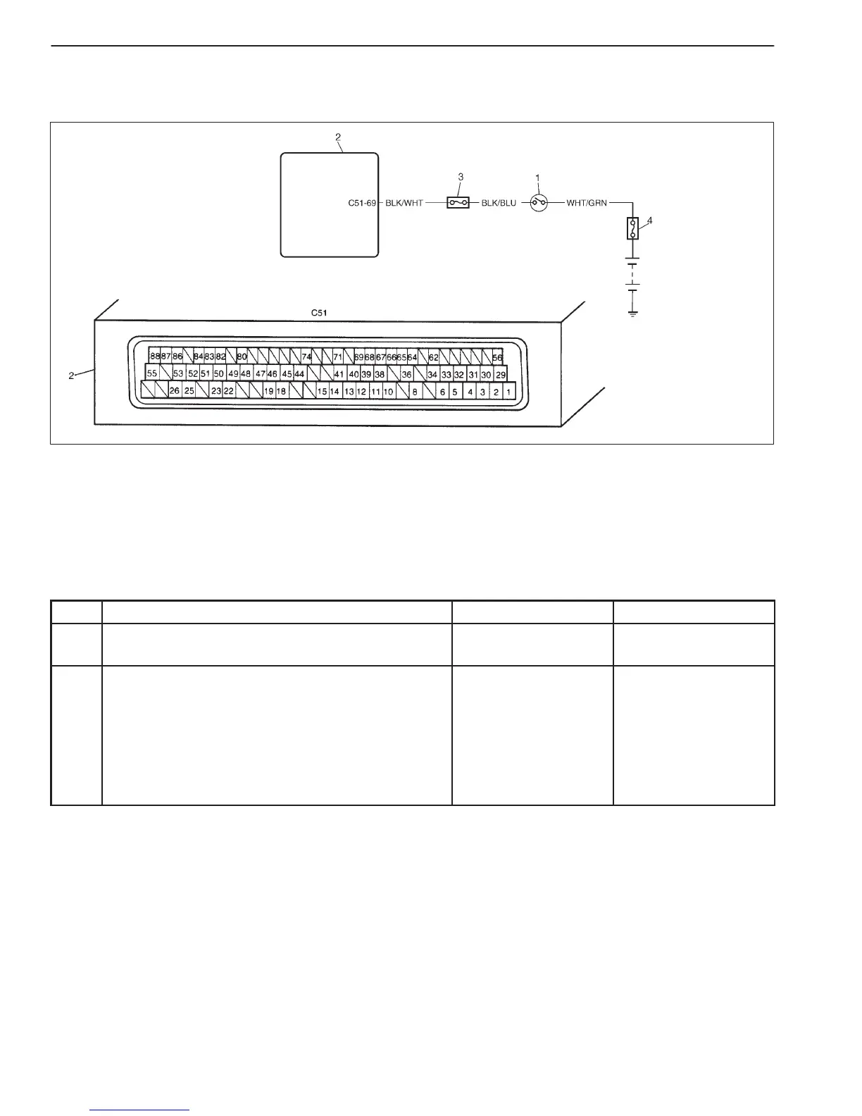
1. Ignition switch
2. ECM
3. “IG METER” fuse (20 A)
4. Main fuse
6-62 ENGINE DIAGNOSIS (RHZ ENGINE WITH SINGLE-CONNECTOR ECM)
DTC P1511 IGNITION SWITCH CIRCUIT MALFUNCTION
WIRING DIAGRAM
DTC CONFIRMATION PROCEDURE
1) Connect scan tool to DLC with ignition switch OFF.
2) Turn ON ignition switch and clear DTC, pending DTC and freeze flame data by using scan tool.
3) Turn off ignition switch and then on.
4) Check DTC and pending DTC by using scan tool.
TROUBLESHOOTING
STEP ACTION YES NO
1 Was “ENGINE DIAG. FLOW TABLE” performed? Go to Step 2. Go to “ENGINE DIAG.
FLOW TABLE”.
2 Check Ignition Signal
1) Remove ECM cover referring to “Voltage Check”
in this section.
2) Check voltage between C51-69 and ground.
D Ignition switch ON: 10 – 14 V
D Ignition switch OFF: 0 V
Is it within specified value?
Poor C51-69
connection.
If it is in good
condition, substitute a
known-good ECM and
recheck.
“BLK/WHT” wire open
or short.

 Loading...


