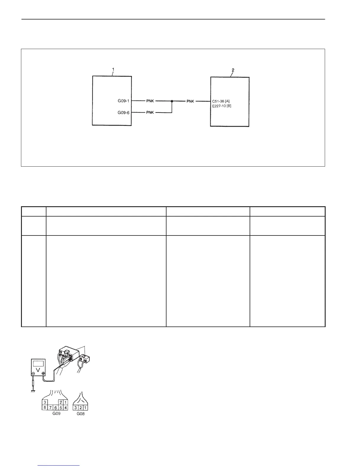
[A] : For vehicle equipped with single-connector ECM
[B] : For vehicle equipped with triple-connector ECM
1. Immobilizer control module
2. ECM
8G-14 IMMOBILIZER CONTROL SYSTEM (IF EQUIPPED)
Fig. 1 for step 2
1. Immobilizer Control Module Coupler
1
DTC42 SERIAL DATA CIRCUIT MALFUNCTION (BETWEEN IMMOBILIZER CONTROL
MODULE AND ECM)
DESCRIPTION
If ECU code is not transmitted from ECM, Immobilizer Control Module sets DTC42.
INSPECTION:
STEP ACTION YES NO
1 Was “Immobilizer Diag. Flow Table”
performed?
Go to Step 2. Go to “Immobilizer Diag.
Flow Table”.
2 1) Disconnect coupler at immobilizer
control module.
2) Check for proper connection to
immobilizer control module at each
terminal.
If OK, check voltage between coupler
terminal below and body ground with
ignition switch ON. See Fig.1.
D G09-6 and body ground
D G09-1 and body ground
Are they 10 – 14 V?
Substitute a known-good
Immobilizer Control Module
and recheck.
D “PNK” wire open
shorted to ground.
or
D Poor C51-36 or
E227-10 terminal
connection
If all above are OK,
substitute a known-good
ECM and recheck.

 Loading...


