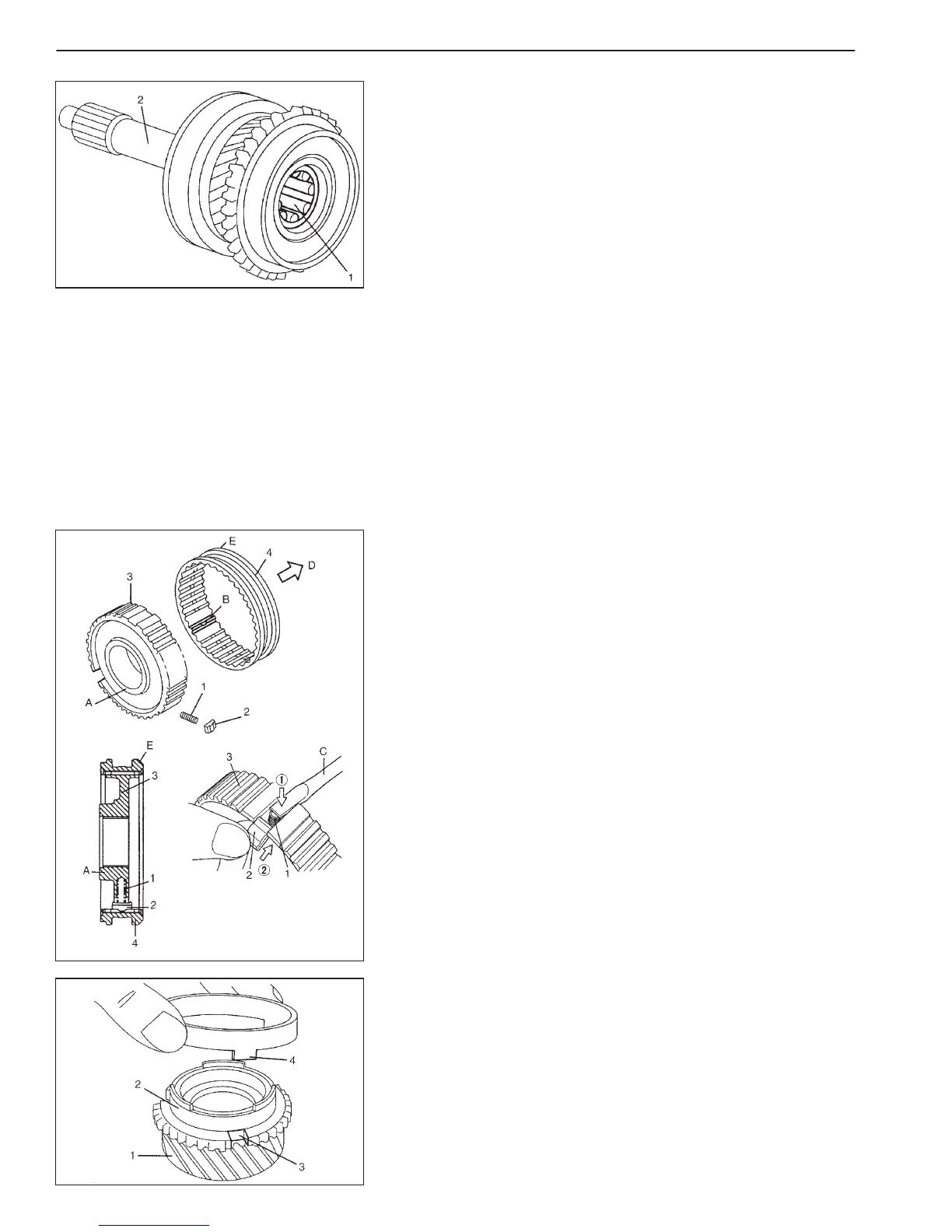
A: Boss
B: Key location teeth
C: Rod
D: Input shaft side
E: Chamfered side
7A2-36 MANUAL TRANSMISSION
3) Apply grease to bearing roller (1) and install it to input shaft (2).
Grease: 99000-25010
MAIN SHAFT ASSEMBLY
NOTE:
D Before installation, wash each part and apply specified gear
oil to sliding faces of bearing and gear.
D Use new circlips on shaft for installation. Don’t reuse cir-
clips.
1) Assemble high speed synchronizer hub (3), sleeve (4), springs
(1) and keys (2) according to the following procedure.
a) Install compression springs (1) and shifting keys (2) to high
speed synchronizer hub (3) as shown in the figure.
b) Slide hub (3) in sleeve (4) so that chamfered side of sleeve
(4) and boss side of hub (3) face opposite as shown in the fig-
ure, also aligning hub slots with key location teeth of sleeve
(4).
2) Assemble 3rd gear (1), synchronizer inner ring (2), synchronizer
cone ring (4) and synchronizer outer ring according to the follow-
ing procedure.
a) Install the synchronizer inner ring (2) to 3rd gear (1), mating
groove of 3rd gear (3) with protrusion of synchronizer cone
ring (4), then attach synchronizer cone ring to 3rd gear as
shown in the figure.

 Loading...


