MANUAL TRANSMISSION 7A2-29
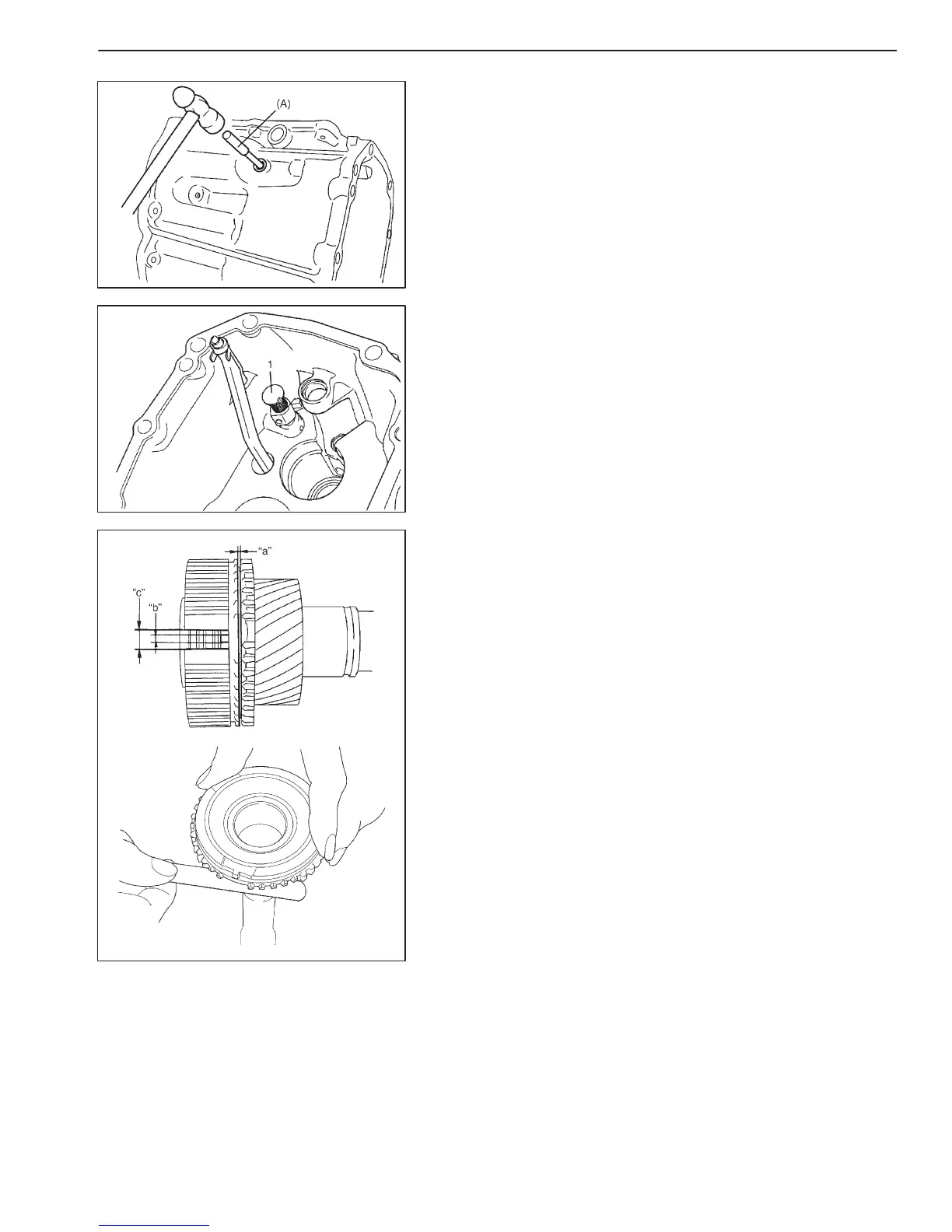
3) Remove pin by using special tool.
Special tool
(A): 09922-85811
4) Pull out interlock cam component (1).
COMPONENTS INSPECTION
INPUT SHAFT ASSEMBLY
Check clearance “a” between synchronizer ring and gear, width of
index protrusion “b” in synchronizer ring, key slot width “c” in high
speed synchronizer hub and each chamfered tooth of gear and
synchronizer ring and replace with new one, if necessary. Also,
check gear tooth.
Clearance “a” between synchronizer ring and gear
(input shaft):
Standard: 0.7 – 1.7 mm (0.028 – 0.067 in.)
Service limit: 0.5 mm (0.020 in.)
Width of index protrusion “b” (input shaft):
Standard: 3.6 – 3.8 mm (0.142 – 0.150 in.)
Service limit: 3.4 mm (0.134 in.)
Key slot width “c” (high speed synchronizer hub):
Standard: 8.0 – 8.1 mm (0.315 – 0.139 in.)

 Loading...


