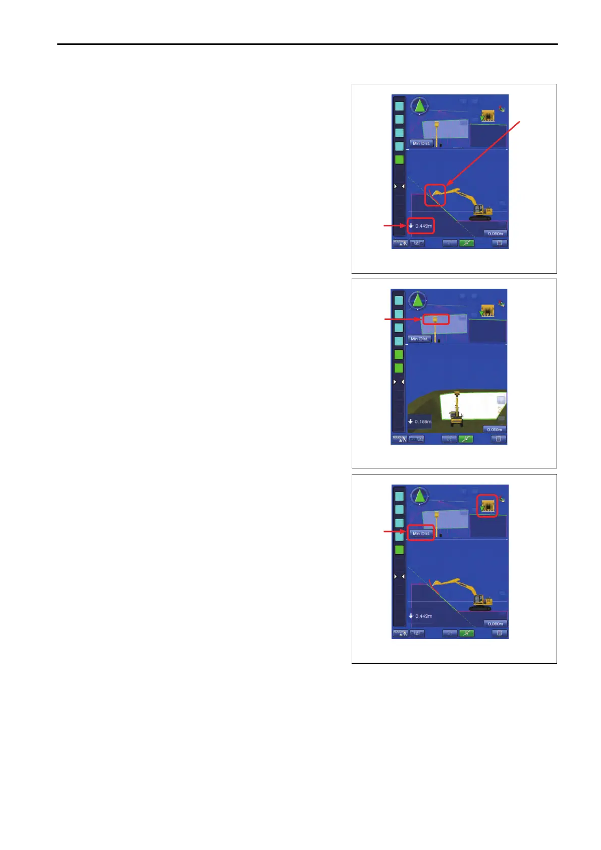
(4) Distance between bucket edge and the design data.
Displays
the minimum distance between bucket edge and the
design data.
(5) Bucket edge trace
The trace of the bucket edge moved is displayed in red line.
The trace is displayed when the bucket edge position is in the
green range of light bar.
(6) Bucket edge position (Plan view)
Green part is displayed as a bucket edge position.
REMARK
Bucket edge position is displayed only in Plan view.
(7) Bucket edge position selection
Tap the Bucket edge position button, and you can select the
bucket edge position to be measured.
Symbol ▽ in front view of bucket indicates the measuring posi-
tion of bucket edge. The sectional view is made at measuring
position of selected bucket edge. Accordingly, the display of
sectional view is changed if the measuring position is changed.
EXECUTIONS ROUGH DIGGING MODE
8-17
 Loading...