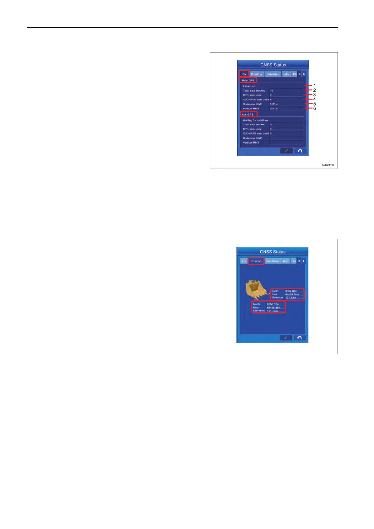
Tap the “Fix” tab to select.
Same
items are displayed in each of “Main GPS” and “Aux
GPS”.
(1) “Initialized!”
States of main GPS and Aux GPS antenna are displayed.
(2) “Total sats tracked”
Number of acquired satellites is displayed.
(3) “GPS sats used”
Number of GPS satellites used for position calculation is dis-
played.
(4) “GLONASS sats used”
Number of GLONASS satellites used for position calculation is
displayed.
(5) “Horizontal RMS”
Horizontal RMS value (error) is displayed.
(6) “Vertical RMS”
Vertical RMS value (error) is displayed.
METHOD FOR DISPLAYING BUCKET EDGE COORDINATES
Bucket tooth tip coordinates can be displayed.
Coordinates of bucket tooth tips at left end and right end are
displayed in set coordinates display.
REMARK
When the bucket width between bucket side cutters is input,
left end and right end denotes the end of the side cutter.
METHOD FOR SETTING SATELLITE POSITION DISPLAY AND ELEVATION
ANGLE
Satellite position and elevation angle in the sky above the machine are displayed.
REMARK
Elevation angle means the upward angle based on the horizon.
CHECK GNSS COMMUNICATION STATUS EXECUTIONS
8-44
 Loading...