Fuse 2
No.
Fuse ca-
pacity
Name of circuit
(1) 5 A
ICT sensor controller, work equipment con-
troller, voice amplifier
(2) 20 A GNSS receiver, control box
(3) 10 A Spare
(4) 10 A Spare
(5) 10 A Spare
(6) 5 A IMU
(7) 5 A Solenoid valve
(8) 20 A Solenoid valve
(9) 20 A Boom secondary drive switch
(10) 10 A Spare
REMARK
• Spare
fuses are installed in the back of the fuse holder lid
at the rear of the operator's seat.
• After using spare fuses, replenish them immediately.
• One spare fuse is installed for each 5 A, 10 A, 15 A, 20 A,
25
A, and 30 A.
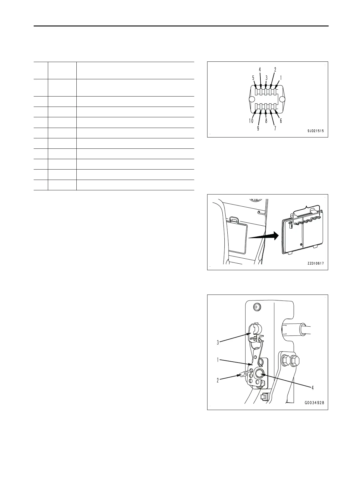
OPERATION OF BATTERY DISCONNECT SWITCH (FOR LOCKOUT/TAGOUT
REGULA
TED REGIONS)
Disconnect-switch can be locked out at the position where
switch-key(3) position is OFF using hasp (1) (Vehicle accesso-
ries) & padlock (2).
NOTICE
• Prepare an appropriate padlock (2) by yourself in ad-
vance.
• If you lost hasp(1)(Vehicle accessories) , please pur-
chase KomatsuPart Number (17A-54-55280) or procure
locally.
• Please perform the following checks before imple-
menting Lockout.
• Lock out disconnect-switch with hasp(1) & pad-
lock(2), In the locked out state, check that the switch-
key(3) does not move to the ON position and the sys-
tem operation lamp(4) does not light up.
OPERATION EXPLANATION OF COMPONENTS
3-35
 Loading...