5.
T
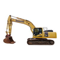
urn the fuel control dial to a point of 2/3 between Low idle
(MIN) position and High idle (MAX) position.
6.
Wait for approximately 5 minutes, and then execute Adjustment Diagnosis referring to “IMU ADJUSTMENT
(7-180)”.
Perform the Adjustment Execute if necessary according to the result of the diagnosis.
7.
Move the R.H. work equipment control lever slowly in the direction to the end of the bucket DUMP side.
8.
Move the R.H. work equipment control lever slowly in the direction to the end of the bucket CURL side.
9.
Repeat steps 7 to 8 a few times.
10.
Move the L.H. work equipment control lever slowly in the direction to the end of arm OUT side.
11.
Move the L.H. work equipment control lever slowly in the direction to the end of arm IN side.
12.
Repeat steps 10 to 11 a few times.
13.
Check that both bucket and arm are most retracted position.
14.
Move the R.H. work equipment control lever slowly in the direction to the end of boom RAISE side.
15.
Move the R.H. work equipment control lever slowly in the direction to the end of boom LOWER side.
16.
Repeat steps 14 to 15 a few times.
17.
Check visually that posture of work equipment displayed on the control box is the same as that of the actual
machine.
METHOD FOR CHECKING AND ADJUSTING BUCKET EDGE ACCURACY
NOTICE
Be
sure to refer to “METHOD FOR CHECKING CONTROL BOX SCREEN DISPLAY”, and perform the
steps 6 to 15 before proceeding.
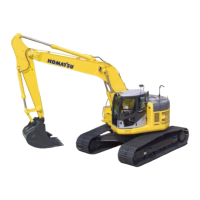
1.
Check that GNSS Status button on the control box lights
up in green.
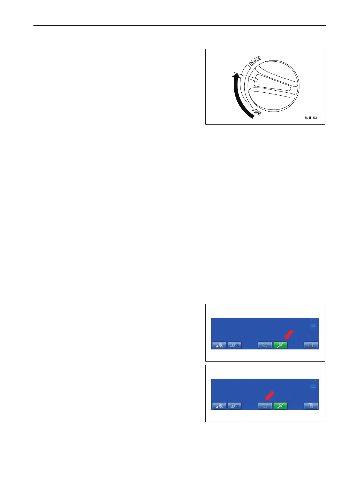
2.
Tap “Blade
edge position” information button on the control
box.
“Blade edge position” screen is displayed.
EXECUTIONS DAILY CALIBRATION
8-33
 Loading...