21 - 4 BeneVision N Series Patient Monitor Operator’s Manual
21.6.3 Connecting the ICG Patient Cable
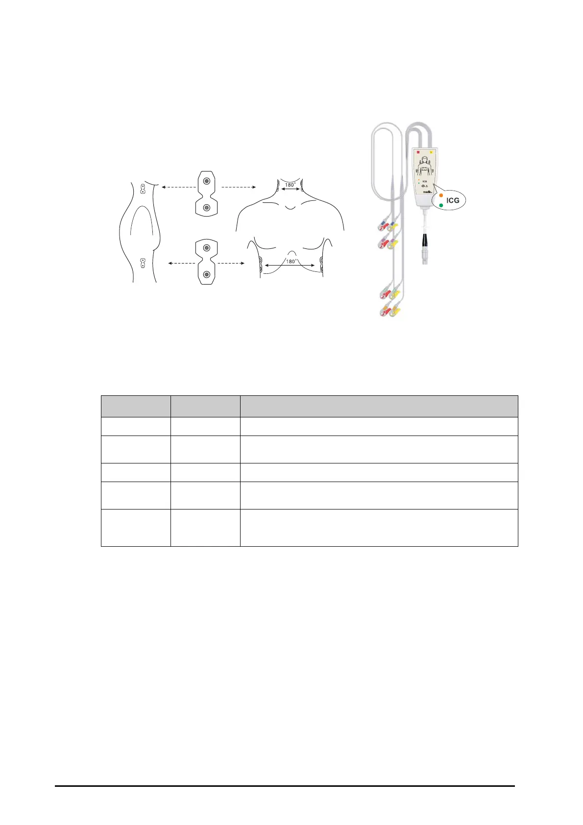
The ICG patient cable is used to connect the ICG module and the sensors on the patient. The left electrode wires
(yellow-colored) and right electrode wires (red-colored) should be connected with the patient sensors by
matching the numbers. For more information, see 21.6.2Placing the ICG Sensors.
The ICG patient cable contains a small box, which includes a cable splitter with integrated electronics. On the
outside of the box two small LEDs (green and orange) display the current function of the patient cable, as
indicated below:
Legend: ○ LED off ☼ LED flashing ● LED on
21.7 Changing ICG Settings
21.7.1 Changing ICG Alarm Settings
To change the ICG alarm settings, follow this procedure:
1. Select the ICG numeric area or waveform area to enter the ICG menu.
2. Select the Alarm tab.
3. Enter the password if required.
4. Set the alarm properties as desired.
21.7.2 Changing Patient Information
To change the patient information, follow this procedure:
Green Orange Description of function
● ○
Measurement is running; sensor contact is good
○ ○
The electronic part of the patient cable is not connected with the power supply;
cable is disconnected or the device is switched off (Power down mode)
☼
○
Patient cable is ready to use, but the measurement has not been started
○
☼
Patient cable has power but the software cannot access the cable; software has
not been started or is not ready for measurement
● ●
Insufficient contact between sensors and patient: at least one lead wire is
disconnected or not properly fixed; sensors are too dry (new sensors are
necessary)
 Loading...