5
"Parameters" Operating Area 03.04
5.2 Tool offsets
5
Ó Siemens AG, 2004. All rights reserved
5-182 SINUMERIK 840D/840Di/810D Operator's Guide HMI Advanced (BAD) – 03.04 Edition
Offsets that are not required must be assigned the value 0 (= default
when the offset memory is set up).
The tool offsets can be entered not only via the operator panel front
but also via the data input interface.
For programming offset data see
/PG/, Programming Guide, Fundamentals
5.2 Tool offsets
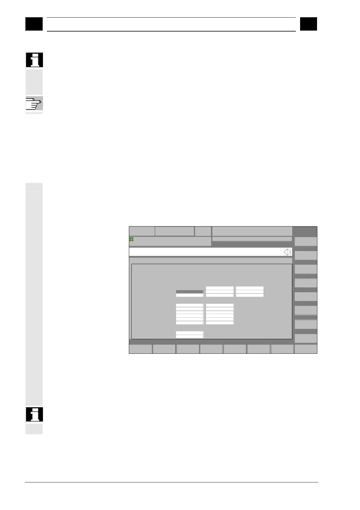
5.2.1 Function and main screen for tool offsets
Tool offset data consist of data which describe the geometry, wear,
identification, tool type and the assignment to parameter numbers.
The unit used for the dimensions of the tool are displayed.
The input field is highlighted.
T No.
Go to...
Overview...
New...
Determine
compens...
Delete...
Tool
offset
R
variables
Setting
data
User
data
Zero
offset
MPF.DIR
TEST.MPF
Channel active
AUTO CHAN1Parameter
T No.
-
D No.
+
D No.
-
:
:
:
:
:
:
T number 1
Tool type 100
C. edge pos. 1
D number 1 No. of c. edges 1
Geometry Wear
Deg.
Base
Tool length comp.
Radius comp.
Length compensation
Length 1 :
mm
Length 2 :
Clear angle
DP25.res :
mm
Length 3 :
mm
Radius : mm
DP7.18.res
DPR.17.res
DP9.18.res
DP10,19.res
DP11,20.res
0.000
0.000
0.000
0.000
0.000
0.000
0.000
0.000
0.000
0.000
0.000
0.000
0.000
0.000
0.000
0.000
0.000
0.000
0.000
0.000
0.000
0.000
Tool offset data
+
Program running
Every offset number contains up to 25 parameters depending on the
tool type.
The number of parameters shown in the window is that for the tool
type.
The maximum number of offset parameters (T and D numbers) can
be set by means of machine data.

 Loading...


