5
03.04 "Parameters" Operating Area
5.3 Tool mana
ement
5
Ó Siemens AG, 2004. All rights reserved
SINUMERIK 840D/840Di/810D Operator's Guide HMI Advanced (BAD) – 03.04 Edition 5-193
5.3.1 Basic tool management functions
The tool management system offers various tools for selection. You
can assign geometric and technological data to the tool types in order
to set up your master tool data. Several versions of each tool can
exist. You can assign the actual data of the tool used (particular tool
data) to these versions.
Tool ma-
nagement
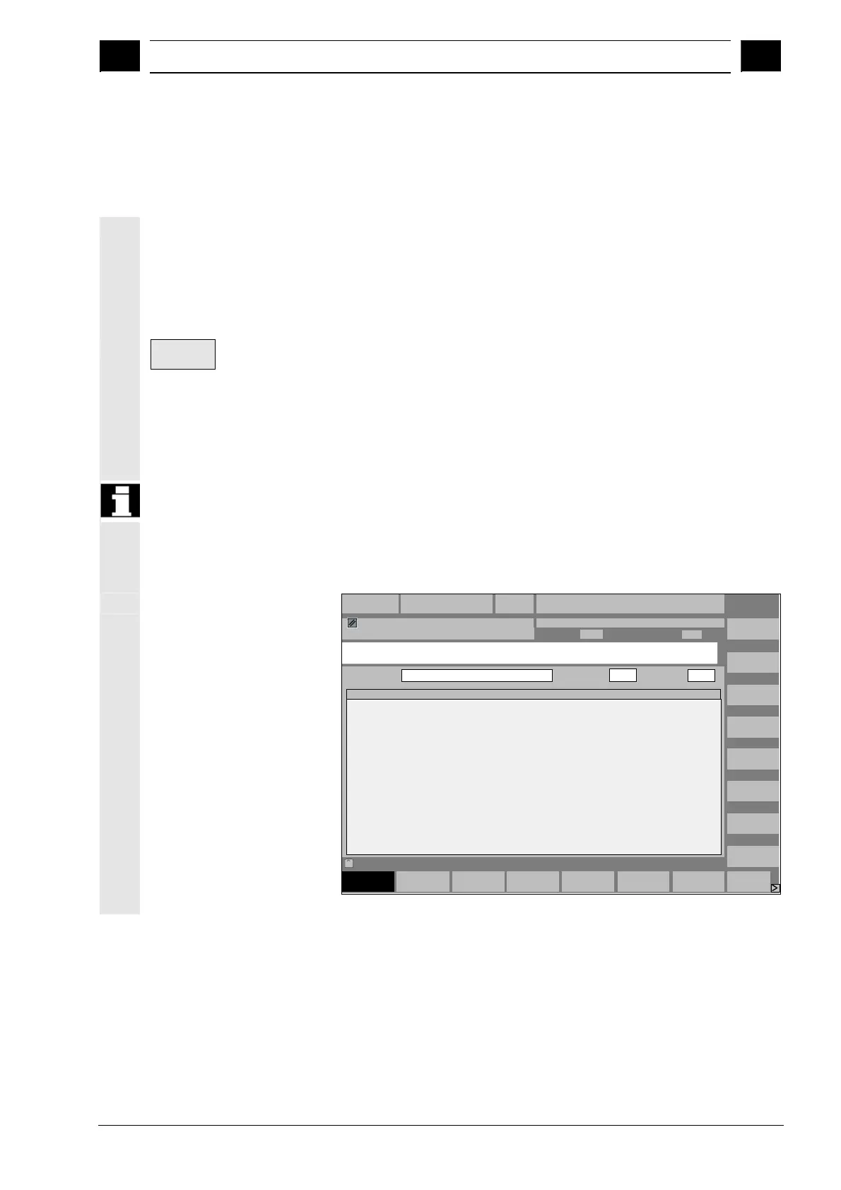
You start the tool management from the operating area "Parameters"
by pressing the softkey.
The machine manufacturer configures which list is to be displayed
when the tool management system is called up. In the example
shown, the "Magazine list" is displayed.
Important
The structure of the table is freely programmable
(configured by the machine manufacturer).
The example shows only one possible case:
Magazine
list 1
Magazine
list
Tool
list
Load Unload
Parameter
Channel RESET
UTOCHAN1
ROV FST
MPF.DIR
LEER.MPF
Magazine
list 2
Magazine
list 3
Tool
data
Buffer
locations
Search and
position
Next
magazine
Relocate
Working
offset list
Magazine list 1
Magazin:
Plätze:
VB:
2 - Kette20
20 0
Pl
1
2
3
4
5
6
7
8
9
10
11
12
13
14
P
-
-
-
-
-
-
-
-
-
-
-
-
-
-
WerkzeugID
newRack860
Wzg1
Wzg2
Wzg3
P
-
F
F
-
-
F
F
F
F
F
F
F
F
F
PTP
1
1
1
1
1
1
1
1
1
1
1
1
1
1
Dupl
1
1
1
1
TNr
1
76
85
7
PTT
1
1
1
1
W
F
F
F
F
W
-
-
-
-
W
G
-
-
-
W
M
-
-
-
W
V
-
-
-
W
-
-
E
-
PV
0
0
0
0
0
0
0
0
0
0
0
0
0
0
WTyp
900
900
900
900
xGeo-L1
11.0000
0.0000
0.0000
0.0000
xGeo-L2
11.0000
0.0000
0.0000
0.0000
Activate
D check
Program aborted

 Loading...


