3
03.04 Example of Operation
3.1 T
ical se
uence of o
eration
3
Ó Siemens AG, 2004. All rights reserved
SINUMERIK 840D/840Di/810D Operator's Guide HMI Advanced (BAD) – 03.04 Edition 3-89
Example of Operation
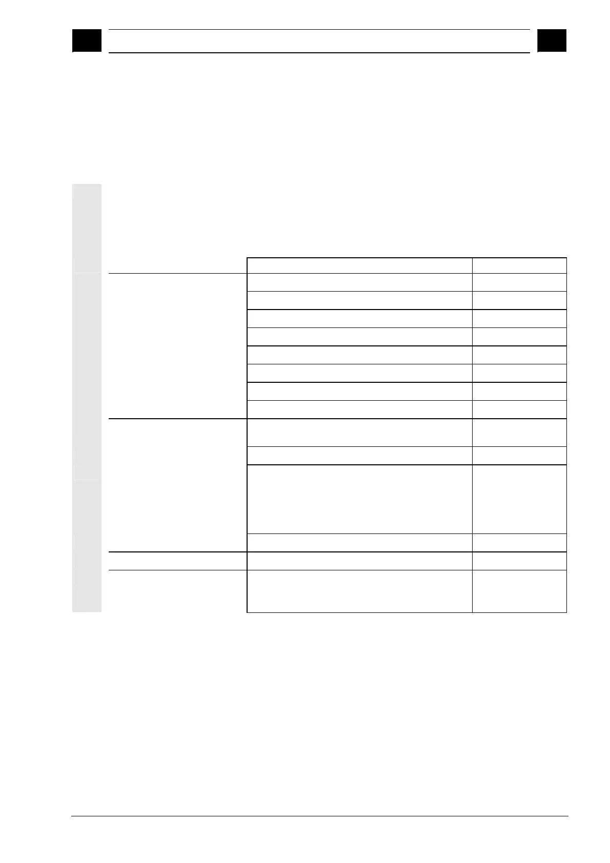
3.1 Typical sequence of operation
To provide support for entry-level users or an orientation guide for
others, this section uses a typical operating sequence (from control
system power-up to back-up of a user-generated part program) to
explain how the functions described can be located.
Step Described in Section
Setup
· Switch on machine
1.3
· Reference point approach
4.3
· Clamp workpiece/blank
· Select tools
· Define workpiece zero for coordinate inputs
· Enter tool offsets
5.2
· Calculate speeds and feedrates
4.2.4
· Define a reference point (scratching)
4.4.6
Enter/test a program
· Create a part program or read
one in via an external data interface
2.6.6
7.5.3
· Select a part program
6.10.5
· Test a program (without a tool)
· Start a part program
(e.g. in single block)
· Edit part program using program editing
function or diagnostics guide/help
4.2.1
2.4.6
4.6.7/2.6.6
8, 2.7
· Optimize a part program
6.9.5
Machine the workpiece
· Insert tool and run machining program
4.2.1
Store the program
· Save a part program
· To hard disk
· Read in/out via RS-232 interface
6.10
6.2
7.5.3/7.5.4
n

 Loading...


