GE VOLUSON
i / VOLUSON
e
D
IRECTION KTI106052, REVISION 10 SERVICE MANUAL
Chapter 3 - Setup Instructions 3-39
3-5-3-6 Installation of the Patient Monitor
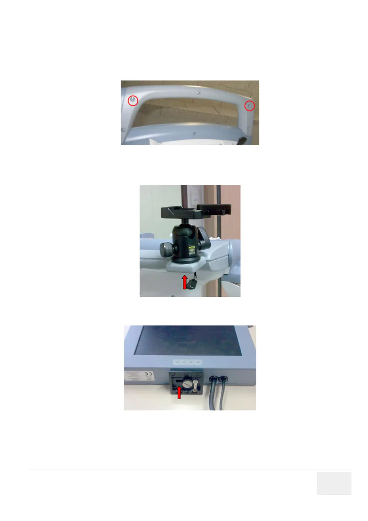
1.) Screw out 2 screws on the Back Handle.
2.) Insert the right and the left Adapter and fix it with the 2 screws (see Figure 3-45, above).
3.) Fix the tripod with a thumbscrew on the Adapter.
4.) Fix the head plate from the tripod with a screw on the monitor.
5.) Connect the VGA-Cable to the VGA Connector and connect the Power Cable on the rear of the
Voluson Station.
Figure 3-45 screw out 2 screws
Figure 3-46 fix the tripod
Figure 3-47 fix the Head Plate
 Loading...


