GE VOLUSON
i / VOLUSON
e
D
IRECTION KTI106052, REVISION 10 SERVICE MANUAL
5-18 Section 5-3 - Front End Processor
Section 5-3
Front End Processor
5-3-1 General Information
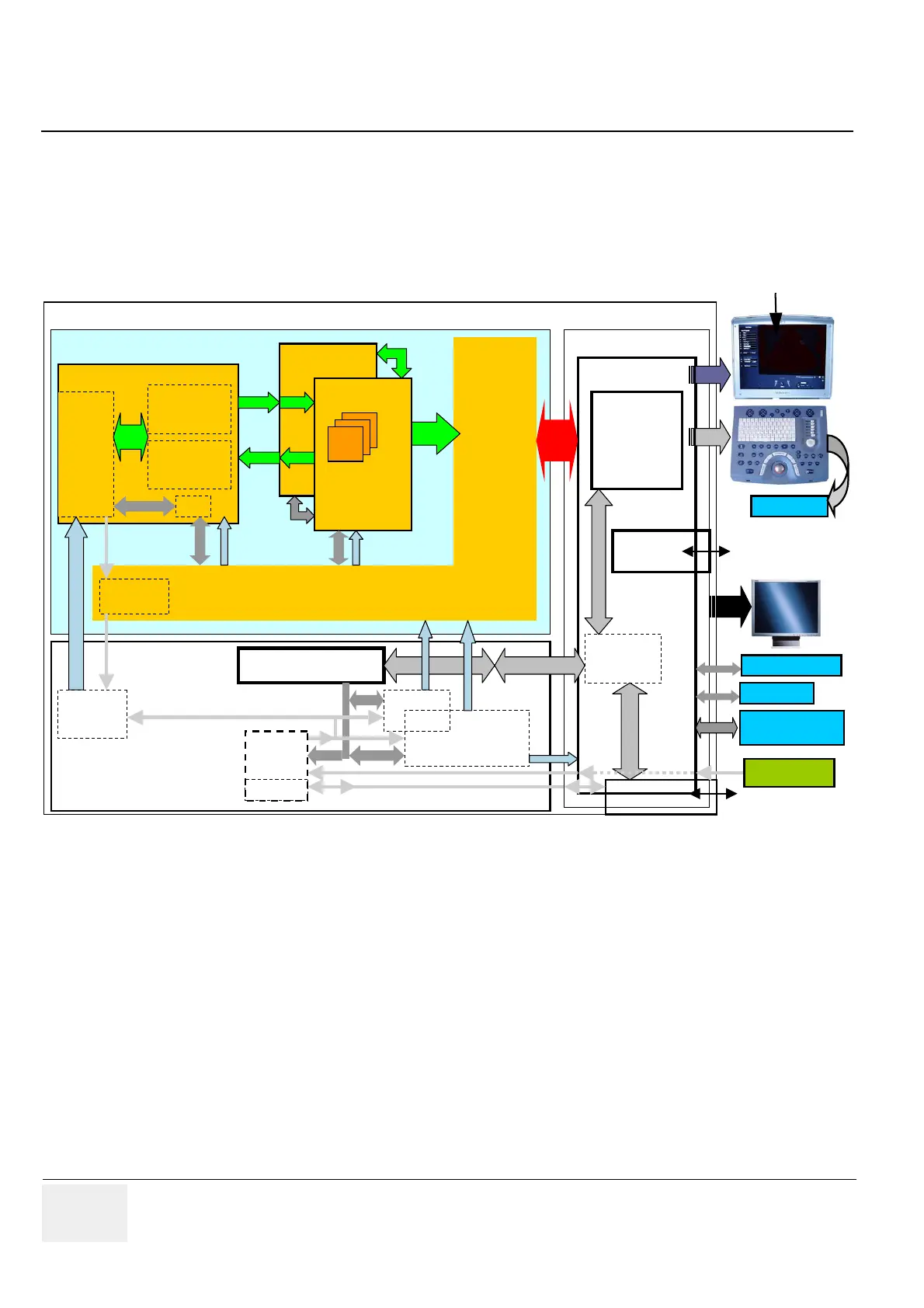
The Voluson i / Voluson e Front End (see diagram in Figure 5-4, above) can be divided into two
subsystems:
1.) MID PROCESSOR SUBSYSTEM which includes:
- RBI Board (Radio Frequency and tissue processing)
For detailed description, see: Section 5-3-2 on page 5-19.
2.) FRONT END SUBSYSTEM which includes:
- RBF Board(s) (each board includes a 32-channel digital Beamformer)
For a detailed description, see Section 5-3-3 on page 5-19.
- RPM (Probe & MUX) Board (includes HVMUX)
For a detailed description, see Section 5-3-4 on page 5-20.
Figure 5-4 Front End - Block diagram
Front End
GPM (RPM)
Back End
Baseboard
GPP (RPS)
SMBus
Rx-MUX
192 to 64
Probe
Connector
192 El.
RBF (1)
32 x (Tx+Rx)
RBI
RBF (2)
32 x (Tx+Rx)
ETX
SBC
Pentium M
1.4GHz
PCI
ControlControl
HV-Supply
LV-Supply Frontend
LV-Supply Backend
Battery
RPC
Controller & Monitoring
Motor
Power
Amplifier
8x
BFIC
2
nd
Monitor
HDD
(80GB)
SupplySupply
Interface for
Docking Station ..
2x USB2.0
PMC - Power
Management
Controller
SMBus
+ Charger
Motor
Controller
System Supply
Tx-MUX
192 to 64
Buffer
DC
Source-
Selector
SMBus
Bottom Assembly
15‘‘ LCD +
Microphone
VGA
LAN 100 MBit
PCMCIA
AC Adapter
Microphone not
available with
SW 8.1.2 and higher
 Loading...


