GE VOLUSON
i / VOLUSON
e
D
IRECTION KTI106052, REVISION 10 SERVICE MANUAL
8-34 Section 8-14 - Replacement of the BBDI Rigid Flex Assembly
8-14-4 Rigid Flex Assy - Removal Procedure (cont’d)
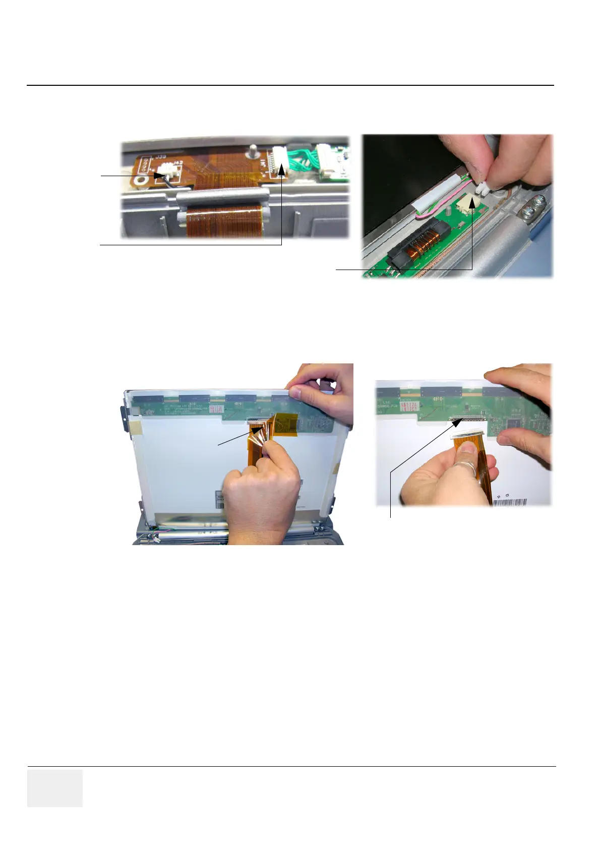
5.) Disconnect the Microphone and the BBDI Inverter cable from the Flex (see: Figure 8-44 below).
6.) Disconnect the LCD Display cable from the Backlight Inverter board (see: Figure 8-44, above).
7.) Carefully lift the LCD Display upwards to gain access to the connector underneath.
Remove the kapton tape from the LCD rear panel and disconnect and remove the BBDI Rigid Flex.
8-14-5 Rigid Flex Assy - Installation Procedure
1.) Connect the new Rigid Flex to the LCD rear panel connector and cover it with the kapton tape,
as shown in Figure 8-45, above.
2.) Place the LCD Display to its original position. Connect the BBDI Inverter cable and the microphone
cable to the Flex (refer to Figure 8-44 on page 8-34).
3.) Fasten the screws that fixate LCD Display onto the Rear Cover (see: Figure 8-43 on page 8-33).
4.) Thread the flex cover and ferrite back into position, as shown in Figure 8-42 on page 8-33.
5.) Insert the BBDI Rigid Flex into the connector and lock it (refer to Figure 8-41 on page 8-33).
6.) Mount the bracket and tighten the 2 screws, as shown in Figure 8-40 on page 8-32.
7.) Mount the LCD Display Frame as described in Section 8-12-5 on page 8-30.
8.) Mount the keyboard module, the battery, the Handle and reconnect the AC adapter; as described
in Section 8-15-5 on page 8-40.
Figure 8-44 disconnect cables
Figure 8-45 remove kapton tape and disconnect Rigid Flex
Micro cable
disconnect
disconnect
BBDI Inverter cable
disconnect LCD cable from
Backlight Inverter board
remove
kapton tape
disconnect the BBDI Rigid Flex
from the LCD rear panel connector
 Loading...


