GE VOLUSON
i / VOLUSON
e
D
IRECTION KTI106052, REVISION 10 SERVICE MANUAL
8-28 Section 8-10 - Replacement of the Handle
Section 8-10
Replacement of the Handle
NOTE: The term "Handle" relates to the Voluson i / Voluson e portable carrying handle.
8-10-1 Manpower
10 minutes
8-10-2 Tools
Use the appropriate flat and Phillips screw drivers as indicated in the Handle replacement procedure.
8-10-3 Preparations
none
8-10-4 Handle - Removal Procedure
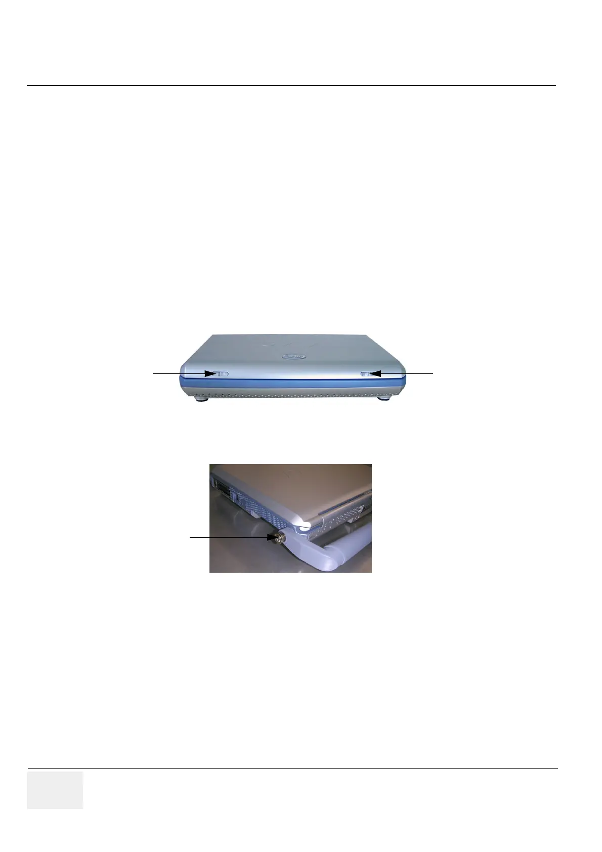
1.) Close the LCD cover, making sure both front latches are securely fastened.
2.) Release the captive screw on either side of the Handle (there are two screws that secure the handle
in position), by turning 1/4 turn in a counterclockwise direction.
3.) Using both hands, pull the Handle slightly apart to release it from the system.
4.) Remove the Handle.
8-10-5 Handle - Installation Procedure
1.) Place a new Handle in position, using both hands to pull the Handle slightly apart in order to slot
the ends into the handle holes on the Voluson i / Voluson e casing.
2.) Carefully fasten each captive screw on either side of the Handle to secure the handle in position,
by turning 1/4 turn in a clockwise direction.
NOTE: When tightening the captive screws, do not use excessive force do not apply more than 1/4 turn;
overtightening will damage the screw thread.
Figure 8-33 Closing LCD Cover
Figure 8-34 Release the captive screws
 Loading...


