GE VOLUSON
i / VOLUSON
e
D
IRECTION KTI106052, REVISION 10 SERVICE MANUAL
Chapter 10 - Care & Maintenance 10-23
10-7-11 Probe Leakage Current Test
10-7-11-1 Definition
This test measures the current that would flow to ground from any of the probes through a patient who
is being scanned and becomes grounded by touching some other grounded surface.
NOTE: Some leakage current is expected on each probe, depending on its design. Small variations in probe
leakage currents are normal from probe to probe. Other variations will result from differences in line
voltage and test lead placement. It is abnormal if no leakage current is measured.
If no leakage current is detected, check the configuration of the test equipment.
10-7-11-2 Tools
For needed tools, see: Section 10-4 "Tools Required" on page 10-5
10-7-11-3 Generic Procedure on Probe Leakage Current
The most common method of measuring probe leakage is to partly immerse the probe into a saline bath
while the probe is connected to the ultrasound system and active.
This method measures the actual leakage current resulting from the transducer RF drive.
Measurements should be made under the test conditions specified in:
• Table 10-10 on page 10-13, or:
• Table 10-11 on page 10-13, as applicable.
For each combination, the probe must be active to find the worst case condition.
NOTE: Each probe will have some amount of leakage current, dependent on its design. Small variations in
probe leakage currents are normal from probe to probe. Other variations will result from differences in
line voltage and test lead placement.
Do not use the probe if the insulating material has been punctured or otherwise
compromised. Integrity of the insulation material and patient safety can be
verified by safety testing according to IEC60601-1.
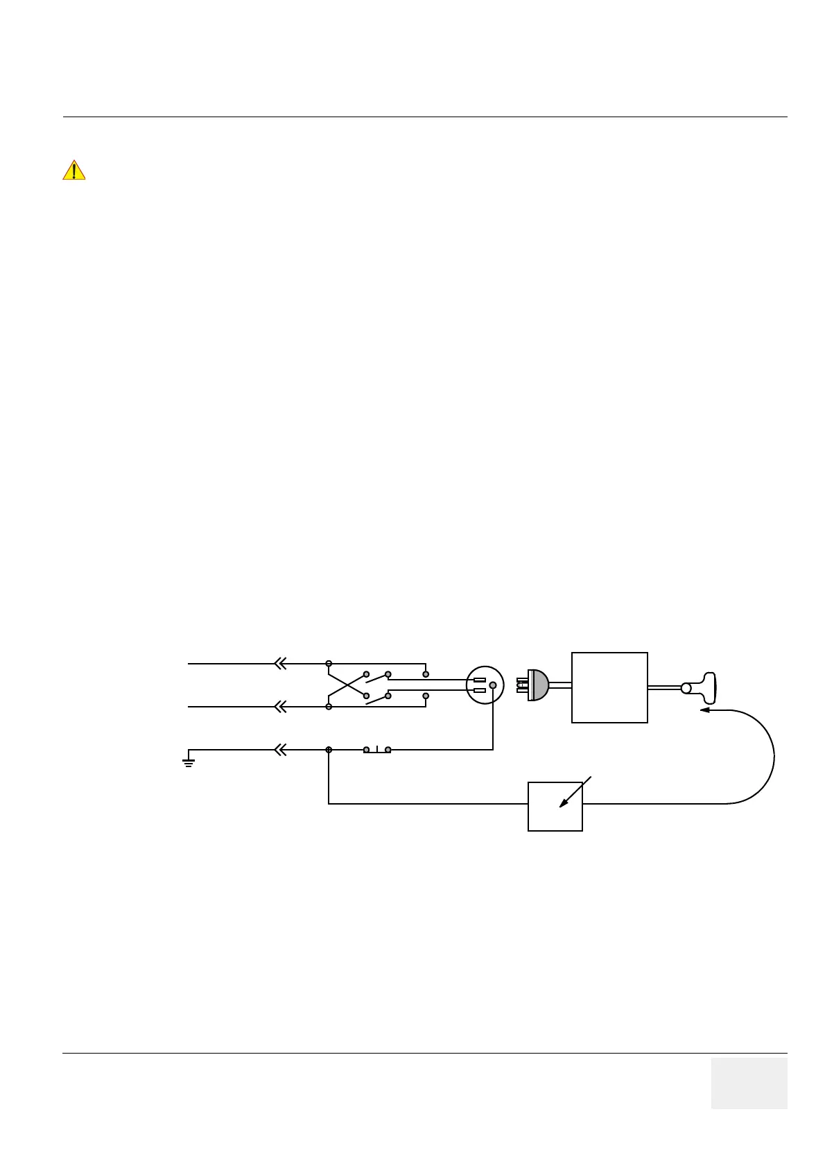
Figure 10-7 Set Up for Probe Leakage Current
POWER
OUTLET
H (BLACK)
POLARITY REVERSING SWITCH
MOMENTARY
SWITCH
N (WHITE)
G (GREEN)
LEAKAGE TEST
METER
CONSOLE
PROBE
 Loading...


