GE VOLUSON
i / VOLUSON
e
D
IRECTION KTI106052, REVISION 10 SERVICE MANUAL
7-6 Section 7-3 - Check Points Voltages
Section 7-3
Check Points Voltages
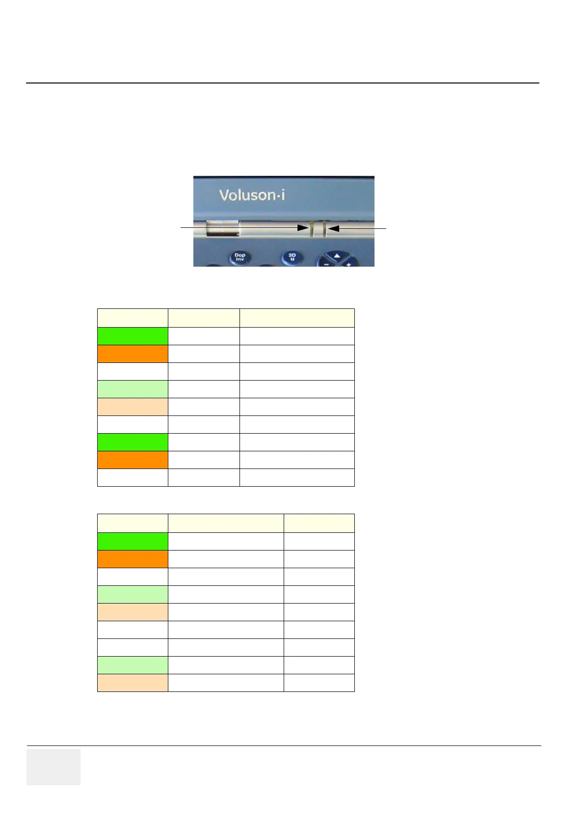
7-3-1 How to check System Status Indicator LEDs
There are two LEDs provided for Indications of Battery and external AC/DC source.
Figure 7-3 Status Indicator LEDs on Voluson i / Voluson e
Table 7-2 left LED - Power Supply (AC Adapter) status
LED Status System Status AC Adapter Status
Green ON AC/DC power OK
Orange ON AC/DC power too low
Off ON AC/DC disconnected
Flashing Green Standby AC/DC power OK
Flashing Orange Standby AC/DC power too low
Off Standby AC/DC power disconnected
Green Full Shutdown AC/DC power connected
Orange Full Shutdown AC/DC power too low
Off Full Shutdown AC/DC not connected
Table 7-3 right LED - Battery status
LED Status System Status Battery Status
Green ON Fully charged
Orange ON Low charge
Off ON Depleted
Flashing Green Standby Fully charged
Flashing Orange Standby Low charge
Off Standby Depleted
Off Full Shutdown (No AC) Any charge
Flashing Green Full Shutdown (AC connected) Fully charged
Flashing Orange Full Shutdown (AC connected) Low charge
left LED
AC Adapter Status
right LED
Battery Status
 Loading...


