GE VOLUSON
i / VOLUSON
e
D
IRECTION KTI106052, REVISION 10 SERVICE MANUAL
Chapter 3 - Setup Instructions 3-79
3-6-5 Transducer Connection
When the probe is connected, it is automatically activated.
Once connected, the probes can be selected for different applications.
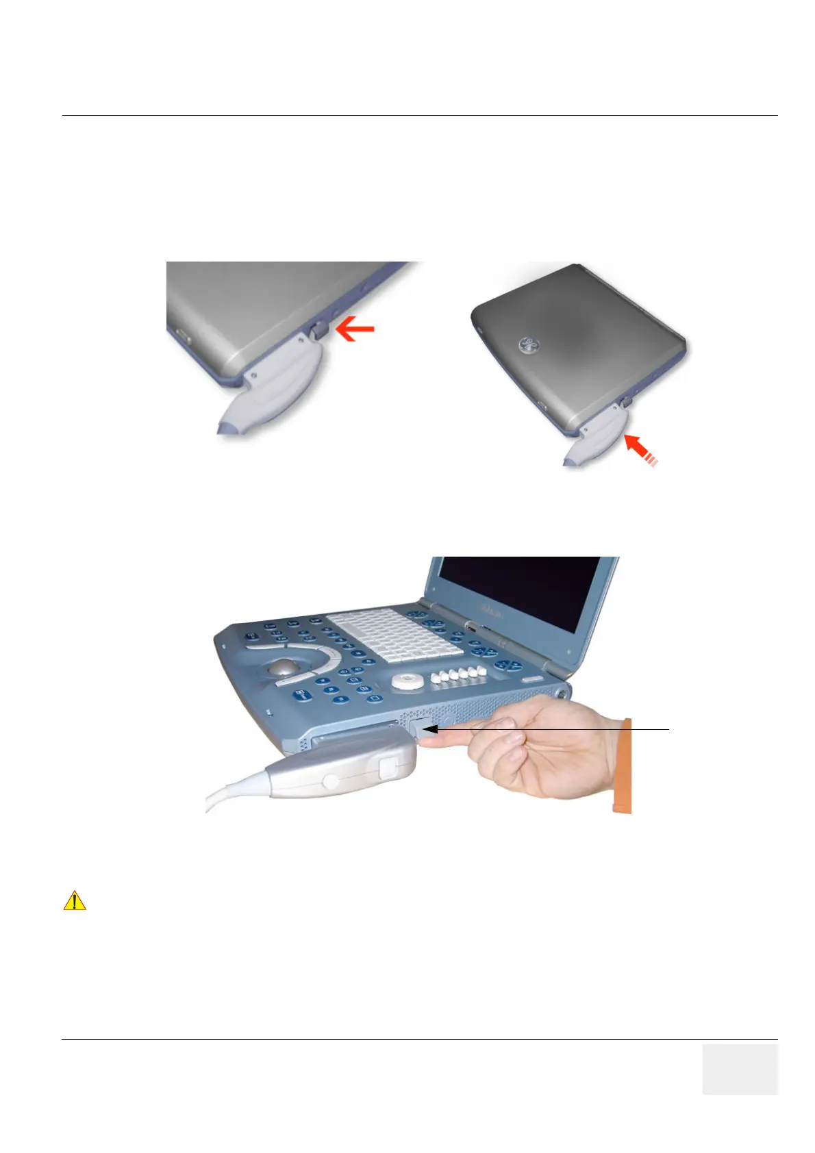
1.) Inspect the probe and probe socket to verify that it is free of debris.
2.) Press the probe connector locking lever downwards. Afterwards align the connector with the probe
port and carefully push it into place, as shown in Figure 3-95 below.
3) Press the connector locking lever upwards to the full vertical position to lock in place.
4.) Carefully position the probe cord so that it is free to move and is not resting on the floor.
NOTE: For Connecting a probe to the Dock Cart please refer to 3.) on page 29.
For Connecting a probe to the Voluson Station please refer to 3.) on page 36.
NOTE: Prior to connecting or disconnecting a probe, freeze the image.
It is not necessary to turn OFF power to connect or disconnect a transducer.
Figure 3-95 Connecting Probe to the Voluson i / Voluson e
Figure 3-96 Securing probe with Locking Lever
!! CAUTION:
Do not bend the probe cable acutely. Fault conditions can result in electric shock hazard.
Do not touch the surface of probe connectors which are exposed when the probe is removed.
Do not touch the patient when connecting or disconnecting a probe.
 Loading...


