GE VOLUSON
i / VOLUSON
e
D
IRECTION KTI106052, REVISION 10 SERVICE MANUAL
Chapter 3 - Setup Instructions 3-69
3-6-1-1 Voltage Level Checks (cont’d)
The following voltage level checks are required whenever the Voluson i / Voluson e system is used
with the Dock Cart or the Voluson Station:
1.) Check the Fuses and Voltage Output Selector setting located on the power supply of the Cart.
If required switch the output selector to correct position and exchange fuses of the power supply,
as described in Section 3-4-4 on page 3-21).
2.) Verify the maximum power requirement.
3-6-2 Power On / Boot Up
1.) Plug a power cable from the destination set into the AC Adapter of the Voluson i / Voluson e.
2.) Plug the power cable to the Voluson i / Voluson e AC Adapter like shown in Figure 3-84 below.
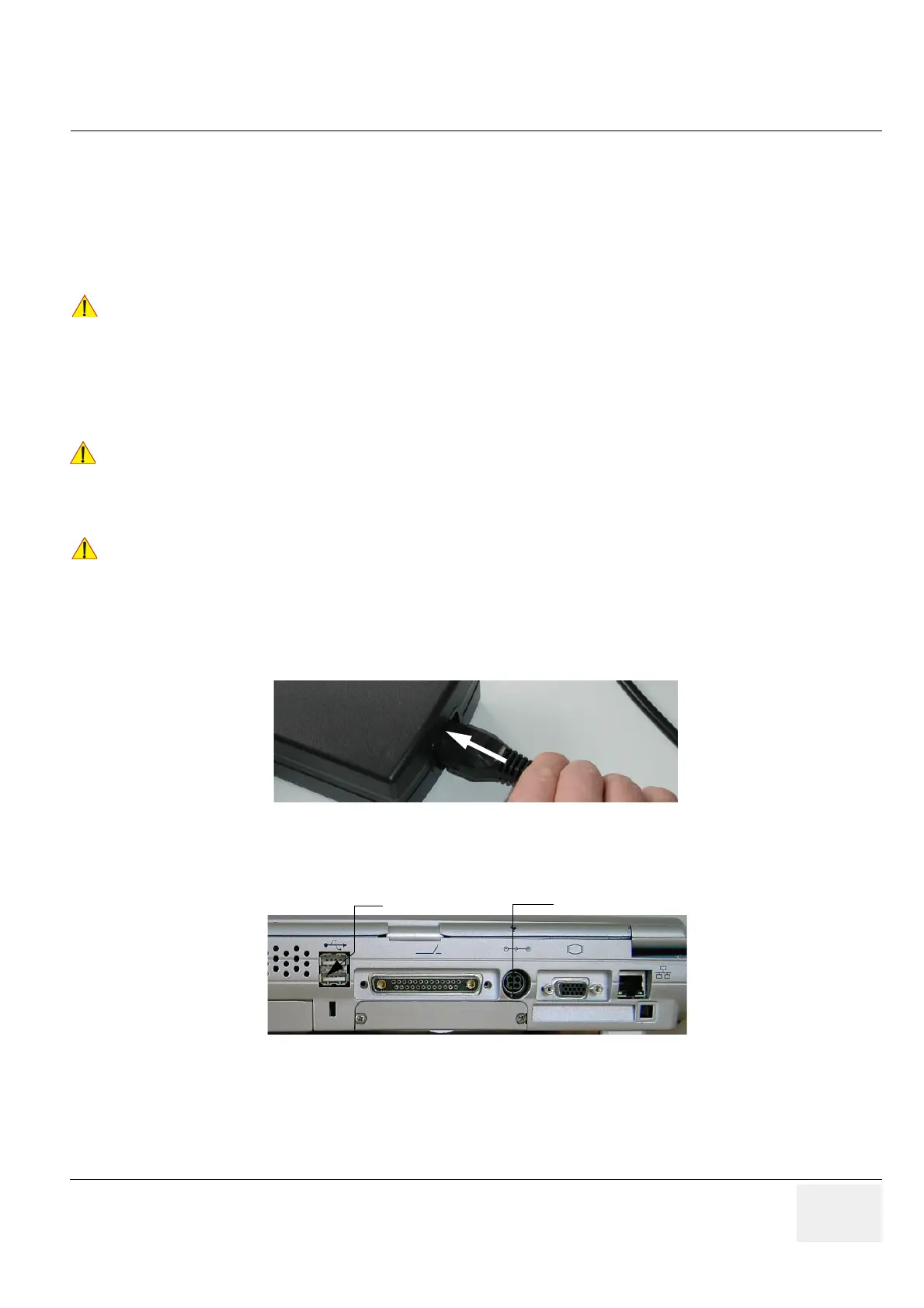
3.) Connect the L-shaped circular plug of the main power cable (via the AC Adapter) to the Power Inlet
DC In connector on the rear of the Voluson i / Voluson e system (see: Figure 3-85).
!! CAUTION:
Before starting the Voluson i / Voluson e or peripherals that are connected to the Cart,
always make sure:
• Rating of power supply fuses is compatible. • Output Selector is in correct position.
The wrong fuses and position of the voltage output selector may cause major damage on
Voluson i / Voluson e and connected peripherals.
!! DANGER:
Failure to provide an adequate earth circuit (ground) may cause electrical shock
and serious injury!
!! NOTICE:
If the system is being used on the different Carts, please follow instructions as described in
Section 3-5-1 "Connection and Usage of the optional Modo Cart" on page 3-25 or in
Section 3-5-2 "Connection and Usage of the optional Dock Cart" on page 3-29 or in
Section 3-5-3 "Connection and Usage of the optional Voluson Station" on page 3-35.
Figure 3-84 AC (main) Adapter connection
Figure 3-85 Main Power Connector (DC In) - Rear Panel
 Loading...


