GE VOLUSON
i / VOLUSON
e
D
IRECTION KTI106052, REVISION 10 SERVICE MANUAL
Chapter 3 - Setup Instructions 3-19
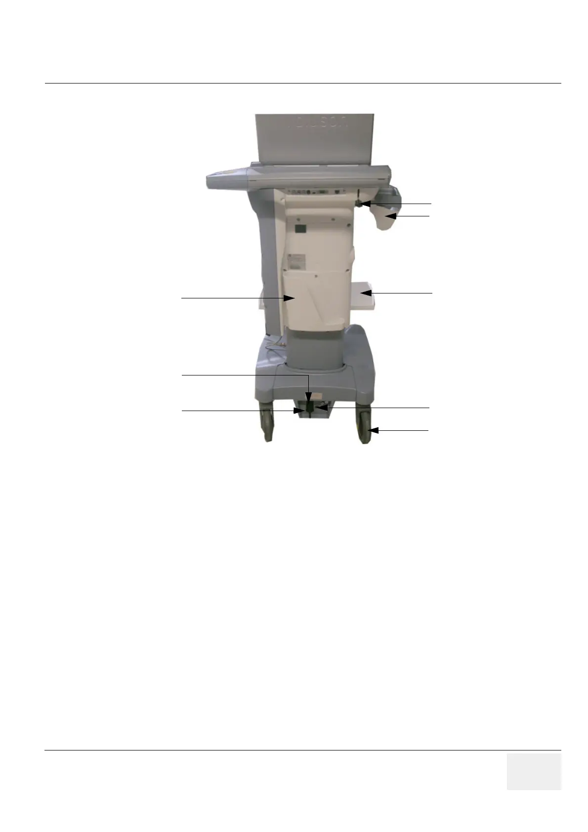
3-4-1-8 Rear View of the Voluson Station
Figure 3-15 Voluson Station - Rear View
1 Release Lever
2 Changeable probe/gel holders
3 Additional Shelf Peripherals (e.g., for Color printer)
4 Storage Tray Back
5 Mains Power Switch
6 Power Supply Fuses for changing between 115V and 230V
7 Voltage Output Selector switch (115V and 230V)
8 Back Caster Wheels
 Loading...


