GE VOLUSON
i / VOLUSON
e
D
IRECTION KTI106052, REVISION 10 SERVICE MANUAL
Chapter 8 - Replacement Procedures 8-37
8-16-4 LCD Display - Removal Procedure (cont’d)
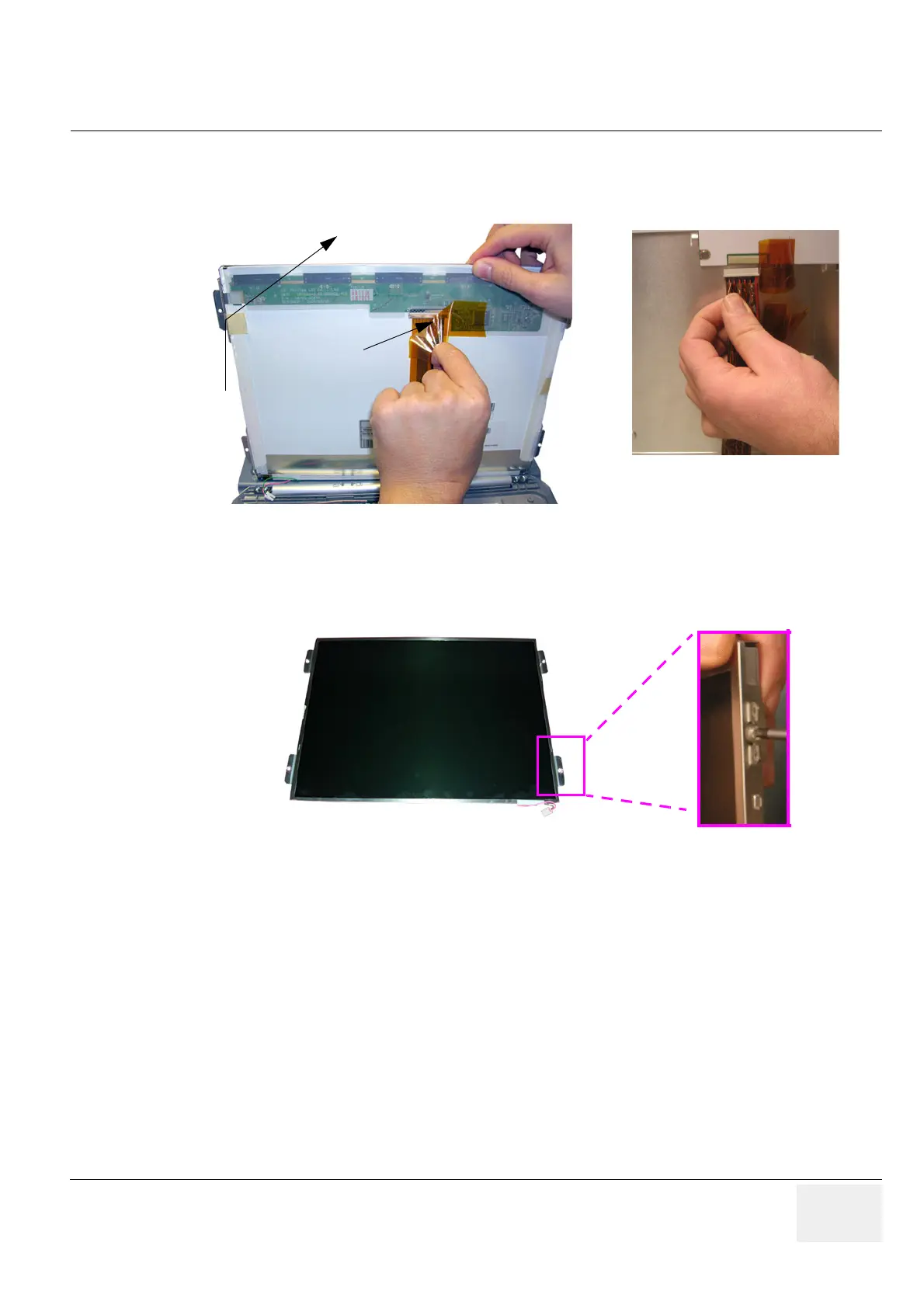
4.) Carefully lift the LCD Display upwards to gain access to the connector underneath.
Remove the kapton tape from the LCD rear panel and disconnect and remove the BBDI Rigid Flex.
5.) Using both hands, carefully remove the LCD Display from the Rear cover assembly.
6.) Turn the LCD Display to the right/left and remove the 4 screws (2 on each side as shown in
Figure 8-50 below) which fixates the aluminium brackets at the LCD Display.
8-16-5 LCD Display - Installation Procedure
1.) Mount the aluminium brackets (1 screw each) on the new LCD Display (see: Figure 8-50, above).
2.) Connect the BBDI Rigid Flex to the LCD rear panel connector and cover it with the kapton tape;
refer to Figure 8-49, above.
3.) Carefully place the LCD Display to its original position. Connect the BBDI Inverter cable,
microphone cable (not available with SW 8.1.2 and higher) and the LCD cable as shown
in Figure 8-48 on page 8-36.
4.) Check that the LCD Display can be tilted upwards and downwards, and that it holds its set position.
5.) Mount the LCD Display Frame as described in Section 8-12-5 on page 8-30.
Figure 8-49 remove kapton tape and disconnect Rigid Flex
Figure 8-50 remove aluminium brackets by loosen the 8 screws
remove
kapton tape
disconnect the BBDI Rigid Flex
from the LCD rear panel connector
 Loading...


