GE VOLUSON
i / VOLUSON
e
D
IRECTION KTI106052, REVISION 10 SERVICE MANUAL
8-30 Section 8-12 - Replacement of the Display Front Frame
Section 8-12
Replacement of the Display Front Frame
8-12-1 Manpower
One person, 15 minutes
8-12-2 Tools
Phillips screwdriver 1 and 2
8-12-3 Preparations
1.) Power Off/Shutdown the system as described in Section 3-6-3 on page 3-72.
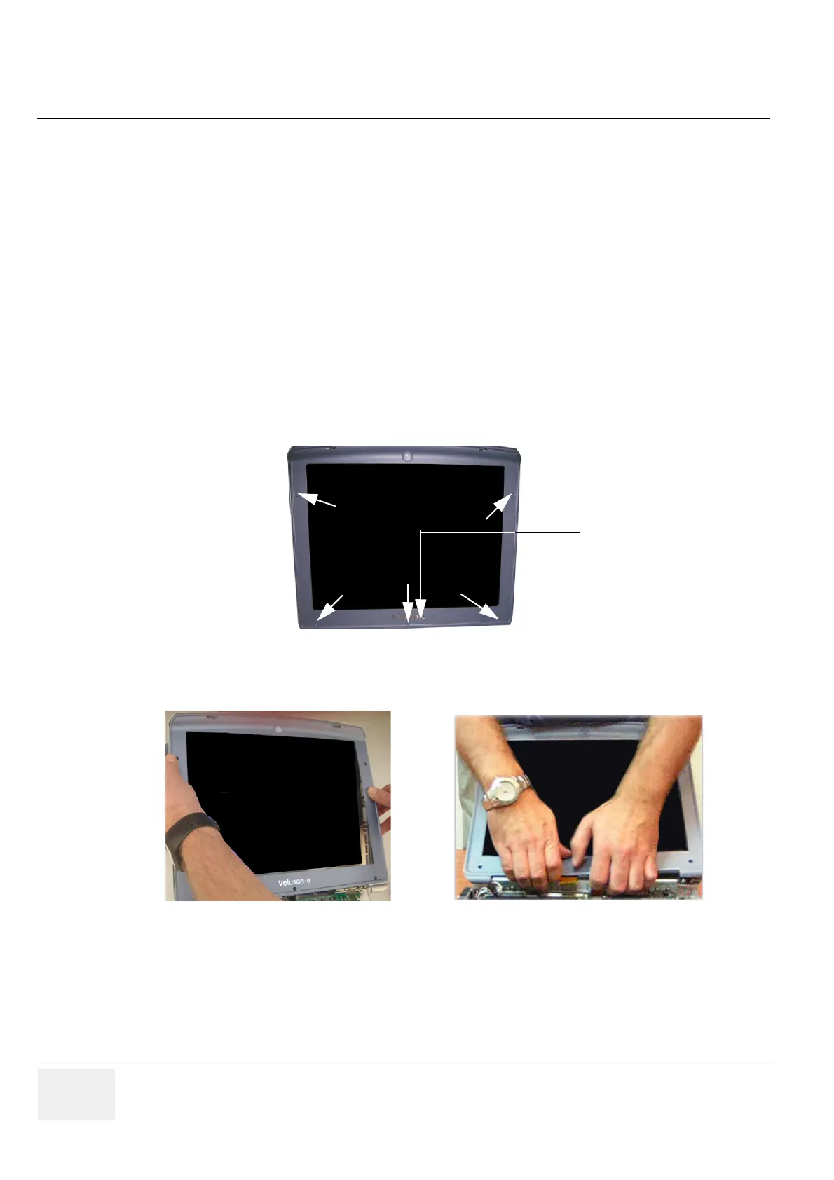
8-12-4 Display Front Frame - Removal Procedure
1.) With the LCD Display in open (upright) position, remove the screw cap from each of the 5 screws
(see: Figure 8-37 below) and then remove the 5 screws that fasten the front frame in position.
2.) With the LCD Display in the fully open position, carefully release the LCD display frame from the
securing clips on all four sides. Use both hands to release and lift it away from the LCD display.
8-12-5 Display Front Frame - Installation Procedure
1.) With the LCD Display in the fully open position, return the front frame to the correct position. Using
both hands, press the frame under the securing clips on all four sides (see: Figure 8-38, above).
2.) Thighten the 5 screws that fasten the LCD frame in position and cover them with the 5 screw caps.
3.) Attach the correct naming sticker on the front frame of the Voluson i / Voluson e system.
Figure 8-37 remove screw caps and screws from the LCD Display Frame
Figure 8-38 carefully remove the LCD Display Frame
“naming sticker” on
display front frame
 Loading...


