 Loading...
Do you have a question about the GE Voluson i BT06 and is the answer not in the manual?
| Type | Ultrasound System |
|---|---|
| Model | Voluson i BT06 |
| Manufacturer | GE Healthcare |
| Display | 15-inch LCD |
| Portability | Portable |
| Application | Obstetrics, Gynecology |
| Imaging Modes | Color Doppler, Power Doppler |
| Software Features | Automated measurements |
| Weight | Approx. 10 kg |
| Power Requirements | 100-240V AC |
| Connectivity | DICOM, USB |
Manual is available in English only; translation services are the customer's responsibility.
Provides a summary of the chapter's content and discusses the purpose of the service manual.
Details conventions used in the manual, including model designations, icons, and safety precaution messages.
Outlines essential safety precautions for operation, service, and repair of the equipment.
Explains EMC, compliance requirements, and electrostatic discharge prevention measures.
Provides contact information for support and assistance from GE.
Provides an overview of the chapter and its purpose.
Details environmental and electrical requirements for the console.
Outlines purchaser responsibilities and site recommendations for installation.
Introduces the chapter and its purpose, including procedures for receiving, unpacking, and configuring equipment.
Provides reminders for average installation time, warnings, and system acclimation.
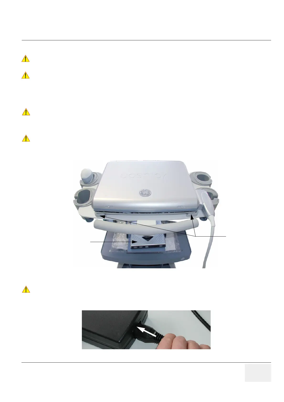
Details procedures for receiving and unpacking the Voluson i / Voluson e ultrasound system and its peripherals.
Covers verification of customer order, inspection of components, and system setup.
Outlines procedures for connecting various peripherals and devices to the system.
Details connecting the unit to a power source and powering on the system.
Provides instructions for installing and configuring various printers.
Covers system setup, including date/time, hospital name, language, and screen lock.
Lists available probes and refers to their part numbers for service.
Guides on configuring software options and parameters.
Explains how to connect the system to remote archives, workstations, or DICOM servers.
Details the procedure for configuring network IP addresses for system connectivity.
Provides a worksheet for recording connectivity and network information.
Ensures documentation for peripheral units is kept with the original system documentation.
Provides an overview of the chapter's purpose and content.
Outlines the general procedure for performing functional checks.
Familiarizes with procedures for checking system's different modes and image optimization.
Details procedures for backing up and restoring system data, presets, and images.
Guides on checking system setup and measurement configurations.
Details how to check the functionality of peripherals.
Provides an overview of the chapter's purpose.
Describes the system's general features, applications, and major components.
Explains the architecture and components of the Front End Processor.
Details the components and functions of the Back End Processor.
Explains the functions and components of the power supply unit.
Illustrates the layout and components of the keyboard and control panel.
Introduces the Service Platform and its access/security features.
Describes the user interface and features of the Common Service Desktop.
Details the specific software/hardware test modules and system setup available on the Service Page.
Provides an overview of the chapter's purpose.
Provides instructions for adjusting color calibration and LCD brightness.
Guides on configuring network adapter settings and speeds.
Details how to adjust the height of the Modo Cart.
Provides instructions for adjusting the height of the Dock Cart's shelves.
Provides instructions for adjusting the height of the Voluson Station.
Guides on setting up the Voluson i / Voluson e keyboard language layout.
Describes how to setup and run tools for maintaining image quality and system operation.
Details necessary information for analyzing malfunctions or returning units to the manufacturer.
Provides procedures for capturing screens and exporting system data for analysis.
Offers GE technicians the possibility to view the customer's desktop and operation system remotely.
Guides on how to start, use, and stop the Auto Tester program for recording processes.
Outlines troubleshooting trees and instructions for common issues like noise and malfunctions.
Lists error messages and their corresponding actions to resolve problems.
Contains replacement procedures for different modules and subsystems.
Details procedures for installing or upgrading system software from DVD or external device.
Provides instructions for replacing the rechargeable battery pack (GPA).
Details the procedure for replacing the LCD display front frame.
Details the procedure for replacing the BBDI rigid flex assembly.
Outlines replacement procedures for Modo Cart components like probe holders and fuses.
Details replacement procedures for Dock Cart components such as trays, covers, and wheels.
Outlines replacement procedures for Voluson Station components like cable holders and probe holders.
Provides an overview of replacement parts available for the Voluson i / Voluson e.
Lists and defines abbreviations used in the manual.
Categorizes mechanical and user-accessible parts for the system.
Illustrates and lists mechanical hardware parts and covers.
Illustrates and lists various keyboard modules and related parts.
Illustrates and lists electronic components of the system.
Lists available software options and upgrades for Voluson i and Voluson e systems.
Lists various cables and their part numbers for system connectivity.
Outlines optional peripherals and accessories, including recording tools, printers, and drives.
Provides an overview of periodic maintenance and the purpose of the chapter.
Explains the importance of maintaining records and quality assurance for the ultrasound system.
Outlines how often care and maintenance tasks should be performed.
Lists the special tools, supplies, and equipment needed for maintenance.
Covers preliminary checks, functional checks, and system checks.
Details electrical safety tests, including leakage current limits and grounding continuity.
Provides troubleshooting steps for excessive leakage current issues.
Guides on downloading and using EQC and IQC forms for quality checks.
Provides a form for recording electrical safety test results.


