GE VOLUSON
i / VOLUSON
e
D
IRECTION KTI106052, REVISION 10 SERVICE MANUAL
8-84 Section 8-20 - Replacement of the Voluson Station Components
8-20-23 Replacement of the Image Resizer Box
8-20-23-1 Manpower
One person, 10 minutes
8-20-23-2 Tools
Phillips screwdriver 1
8-20-23-3 Preparations
1.) Power Off/Shutdown the system as described in Section 3-6-3 on page 3-72.
2.) Remove the complete lever.
3.) Remove the Top Shelf Bottom Rear Cover as described in Section 8-20-13 on page 8-73.
8-20-23-4 Image Resizer Box - Removal Procedure
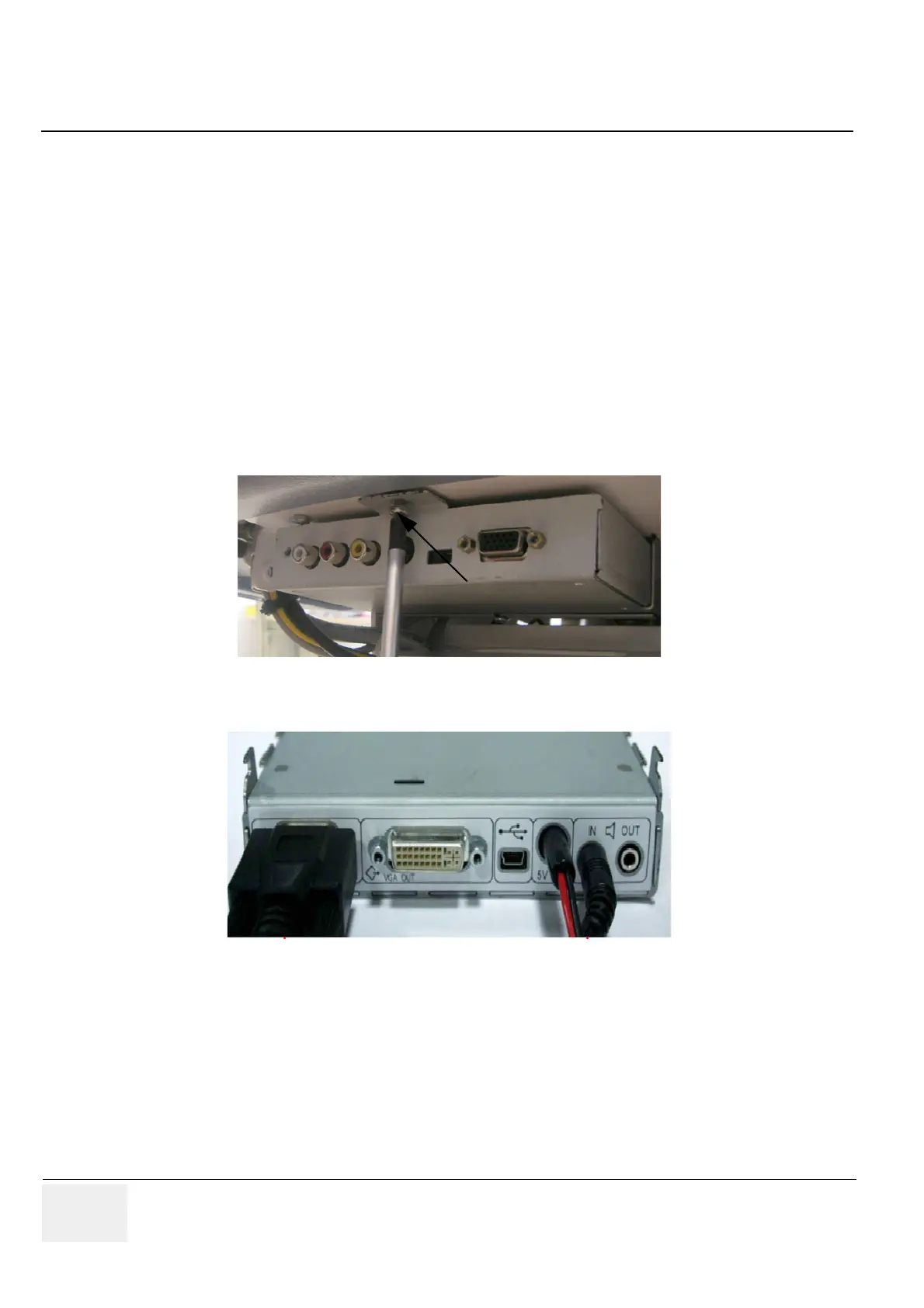
1.) Screw off 1 screw.
2.) Disconnect the cables (VGA, Power, Chinch).
8-20-23-5 Image Resizer Box - Installation Procedure
1.) Connect the cables to the new Image Resizer Box and place it on its original position.
2.) Fasten it with the screw.
3.) Mount the Top Shelf Bottom Rear Cover as described in Section 8-20-13-5 on page 8-73.
4.) Mount the complete lever at its original position.
Figure 8-105 screw off 1 screw
Figure 8-106 disconnect the cables
 Loading...


