GE VOLUSON
i / VOLUSON
e
D
IRECTION KTI106052, REVISION 10 SERVICE MANUAL
Chapter 3 - Setup Instructions 3-61
3-5-14-1 Direct Connection to the Voluson i / Voluson e system (cont’d)
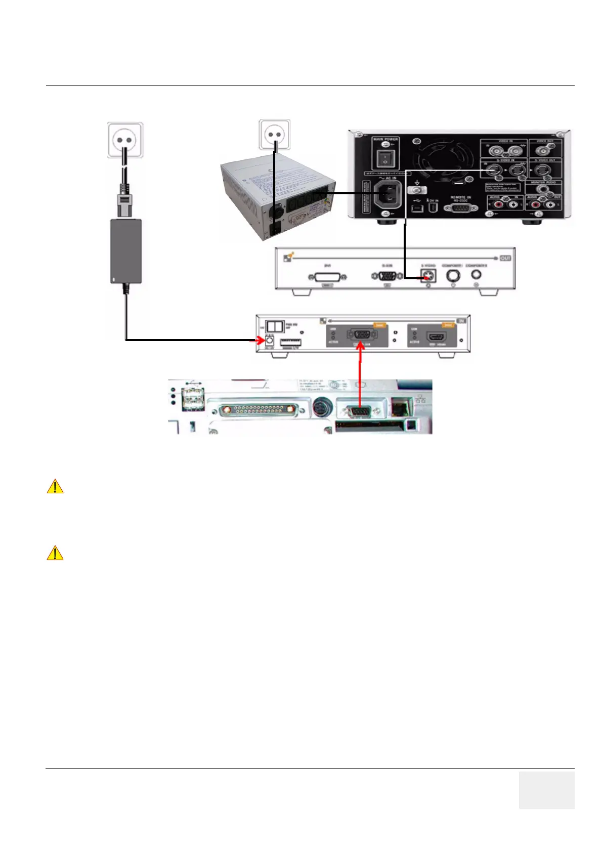
1.) Connect one end of the VGA cable to SVGA OUT located on the Voluson i / Voluson e rear
connector panel.
2.) Connect the other end of the VGA cable to RGB IN on the video converter (rear).
3.) Connect one end of the S-Video cable to S-VIDEO OUT on the video converter.
4.) Connect the other end of the S-Video cable to S-VIDEO IN at the rear of the DVD recorder.
Figure 3-75 Connection Scheme - DVD Recorder with Video Scan Converter Ophit
!! CAUTION:
When connecting the DVD Recorder/Video Converter directly to the system, it is necessary to use an
additional power source. As a safety requirement, the DVD Recorder internal AC/DC and the Video
Converter AC/DC (supplied with the Video Converter) must be medical grade (conforming
60601-1 standard) or the safety must be ensured by the use of a medical grade isolation
transformer.
!! NOTICE:
Auxiliary equipment with direct mains connection requires galvanic separation e.g. by use of a medical
grade isolation transformer.
Power
Video Converter (rear)
Supply
power
socket
Video Converter (front)
isolation
transformer
Voluson i/e (rear)
 Loading...


