GE VOLUSON
i / VOLUSON
e
D
IRECTION KTI106052, REVISION 10 SERVICE MANUAL
5-28 Section 5-5 - Power Supply Unit
Section 5-5
Power Supply Unit
5-5-1 Introduction
The Power Supply Unit (GPP) provides the Voluson i / Voluson e system with both Low Voltage and
High Voltage power, and also enables recharging of the battery.
The GPP Unit controls following main functions:
- Input switching stage – selects between the external DC source or internal battery
- Back End Low Voltage power supply (LVPS)
- Standby power supply
- Front End Low Voltage power supply (LVPS)
- Front End High Voltage power supply (HVPS)
- Battery charger
- PS ON/OFF control
- Micro controller and circuitry (used for monitoring, charger control and auxiliary functions).
The PS communicates with the host CPU via the SMBus.
- 4D motor power - amplifier
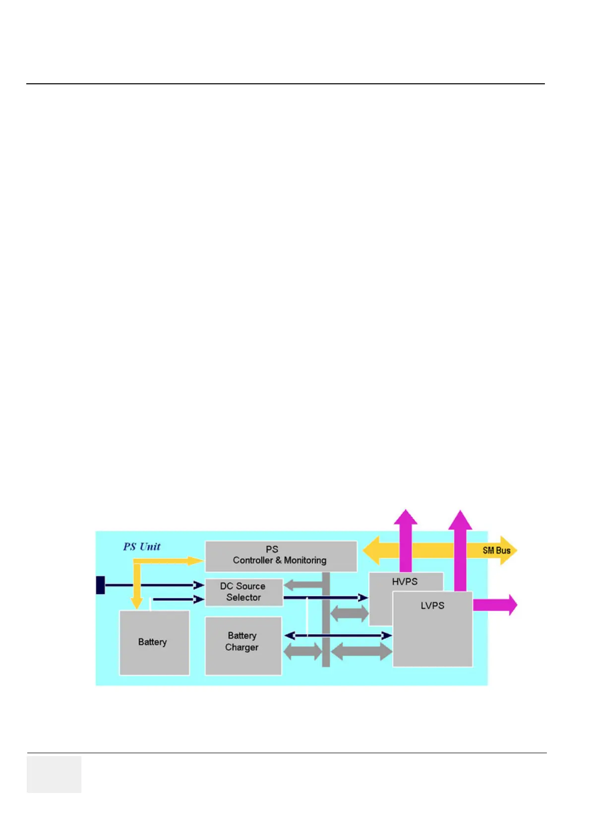
5-5-2 Power Supply Unit Components
As shown in Figure 5-10 below, the Power Supply Unit comprises the following components:
• Rechargeable Battery
• PS Controller and Monitor
• DC Source Selector
• Battery Charger
• High Voltage Power Supply (HVPS)
• Low Voltage Power Supply (LVPS)
Figure 5-10 Voluson i / Voluson e Power Supply Unit Components - Block Diagram
 Loading...


