T200 User's Manual SECTION 5: QUICK START
PAGE 5-10
5.1.3.9 Step 9:- Enabling the T200 and Causing Movement of the Motor
Apply 230Vac mains power to the mains inputs of the T200. Wait 5s for completion of softstart. After this time the
T200 should close the Power Ready Relay to indicate a successful soft start-up. Note that this relay should be used in an
interlock fashion to signal to all connected T200s that they can be enabled. Enabling in this case means that power is
applied to the output inverter bridge and means that the motor can be activated.
If the Power Ready output indicates that no fault exists on a T200 with integral PSU then the T200 and all connected
T200 without integral PSU may be enabled (i.e. high power applied to the motor windings).
The T200 may be enabled using the hardware ENABLE digital input of J1, which must be set active to allow the
application of high power to the motor. When the hardware enable is active, the T200 may be enabled and disabled
under software control using the F3 key when WinDrive is active. Note however that no T200 should be enabled before
the Power Ready relay has closed, including the T200 that contains the integral PSU.
If the user followed the recommended setup (Velocity mode, Function Generator reference), then the T200 may now be
enabled and the motion of the connected load checked. Note that Section 10 contains recommendations for
troubleshooting.
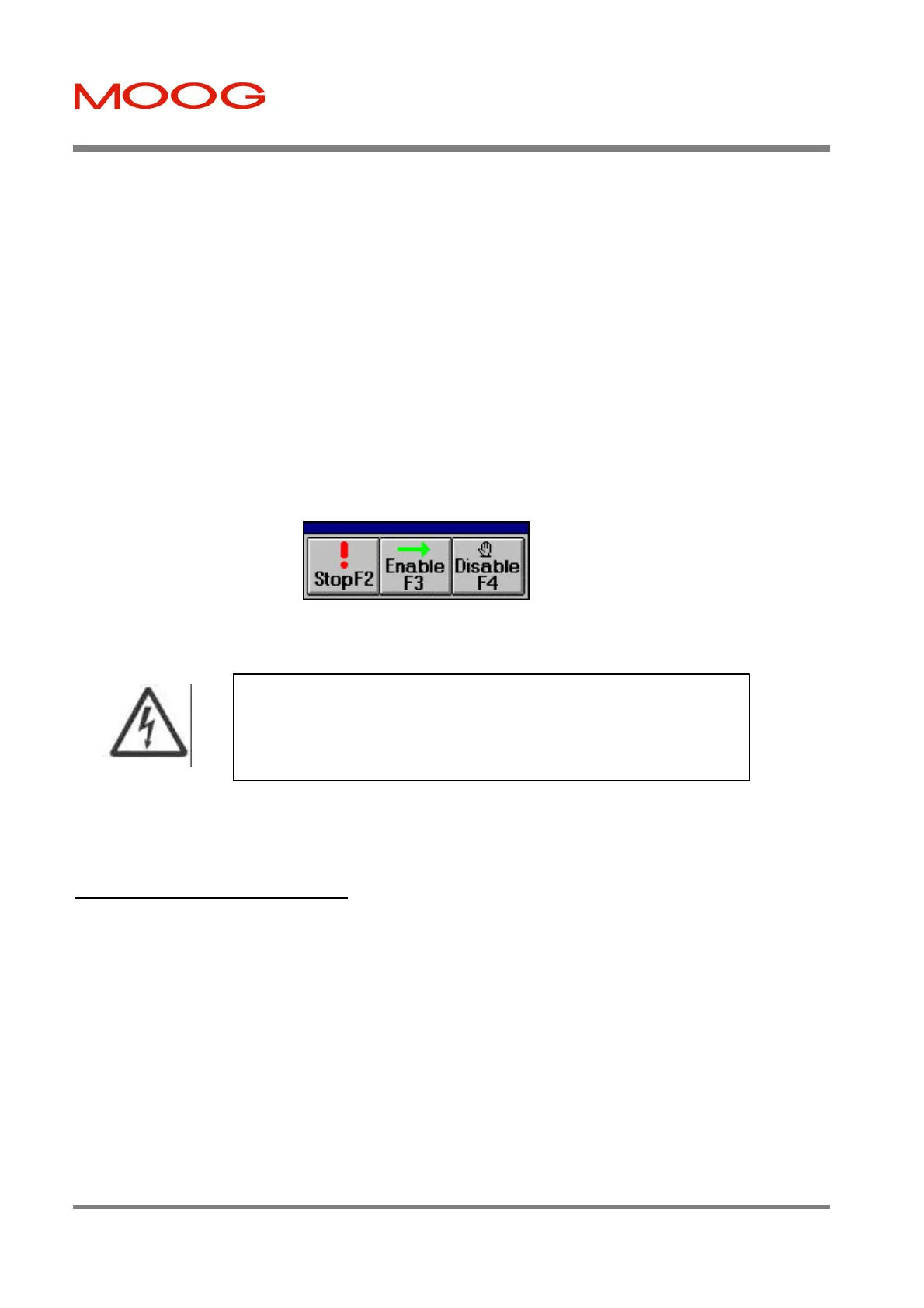
Figure 5.9:- Enable/Disable/Quick-Stop Floating Toolbar.
When finished, close down WinDrive by left clicking on the File-Exit menu item, or by selection of other standard
Windows program exit mechanisms.
5.1.4 Power-Down Sequence
Disable the Power Amplifier (i.e. remove power to the motor windings). Save the parameters to non-volatile storage
using ‘Save to EEPROM’ in the ‘File’ – Menu.
Remove 230Va.c. mains. Wait at least 5minutes for the fast bus discharge. Note that in abnormal circumstances, if
damage has occurred to the T200 then it will take at least 5 minutes for the internal high voltage to discharge.
Remove 24Vd.c. or 120 Va.c. logic backup power from the T200
The sequences described above are those recommended for normal power up/down events. There will be circumstances
where these sequences cannot be maintained (e.g. mains power failure). The T200 is designed to survive simultaneous
mains and 24Vd.c. or 120 Va.c. logic backup power removal.
The above short sequence gives the user a step by step procedure on how to install, set-up, and operate the Moog T200
integrated servo-drive in its most basic format. The T200 drive system has many advanced features necessary for typical
servo applications that are not covered here.
- Ensure that all listed safety precautions are observed when
performing this tuning operation. Ensure that the motor is securely mounted on
a suitable fixture. Sudden and considerable movement of the motor, with a risk
of serious injury, will occur during high speed reversals if the motor is not
securely mounted.
Artisan Technology Group - Quality Instrumentation ... Guaranteed | (888) 88-SOURCE | www.artisantg.com

 Loading...


