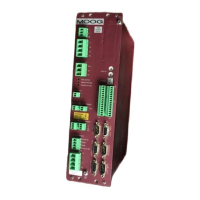
T200 User's Manual SECTION 6: T200 FUNCTIONAL OVERVIEW
PAGE 6-2
TABLE OF CONTENTS
T200 FUNCTIONAL OVERVIEW ..............................................................................................................................6-1
6.1 INTRODUCTION.................................................................................................................................................6-5
6.2 T200 FUNCTIONALITY OVERVIEW..................................................................................................................6-6
6.2.1 Analog Command Interface......................................................................................................................6-6
6.2.2 Controller Area Network (CAN) Interface Mode.....................................................................................6-7
6.2.3 Stepper Motor Interface Mode..................................................................................................................6-8
6.2.4 Digital Inputs Velocity Interface Mode ....................................................................................................6-9
6.2.5 Standalone Motion-Controller Custom Interface Mode ("Point") ..........................................................6-10
6.3 T200 CONVENTIONS ......................................................................................................................................6-11
6.3.1 Direction of Rotation ..............................................................................................................................6-11
6.4 POWER INTERFACE SECTION ........................................................................................................................6-12
6.4.1 T200 Model Types and High Power Interface ........................................................................................6-12
6.4.2 High Power Section Description.............................................................................................................6-12
6.4.2.1 High Power Circuit Description ...........................................................................................................................6-15
6.5 INPUT AND OUTPUT FUNCTIONAL DESCRIPTION..........................................................................................6-17
6.5.1 Reference Analog (± 10V Command) Input ............................................................................................6-17
6.5.2 Spare Analog (Analog Torque Limit) Input ...........................................................................................6-17
6.5.3 TP1 Analog Output.................................................................................................................................6-17
6.5.4 TP2 Analog Output.................................................................................................................................6-18
6.5.5 Limit Switch Function............................................................................................................................6-18
6.5.6 Power Ready Input..................................................................................................................................6-19
6.5.7 Automatic and Manual Power Settings...................................................................................................6-19
6.5.8 Torque-Velocity Control Mode switching..............................................................................................6-20
6.5.9 Rotation Direction...................................................................................................................................6-20
6.5.10 Programmable Speed Functions..............................................................................................................6-21
6.5.11 Thermal Limiting Indication...................................................................................................................6-21
6.5.12 Drive Power Status .................................................................................................................................6-22
6.5.13 Speed Torque Achieved Indication.........................................................................................................6-23
6.5.14 System Ready Indication ........................................................................................................................6-24
6.5.15 Brake Control..........................................................................................................................................6-24
6.6 INTERNAL FUNCTION GENERATOR...............................................................................................................6-25
6.6.1 Torque and Velocity Function Generator................................................................................................6-25
6.6.2 Position Function Generator ...................................................................................................................6-26
6.7 CONTROL LOOP OVERVIEW..........................................................................................................................6-28
6.7.1 Torque Mode...........................................................................................................................................6-28
6.7.1.1 Torque Command Sources ...................................................................................................................................6-30
6.7.1.2 Torque-Command Analog Offset Adjust..............................................................................................................6-30
6.7.1.3 Rate Limiting in Torque-Mode.............................................................................................................................6-31
6.7.1.4 Programmable Torque Limiting in Torque Mode.................................................................................................6-32
6.7.1.5 Programmable Velocity Limiting in Torque Mode ..............................................................................................6-32
6.7.1.6 Analog Torque Limiting in Torque Mode ............................................................................................................6-33
6.7.1.7 Torque Mode Functional Block Diagram .............................................................................................................6-34
6.7.2 Velocity Mode ........................................................................................................................................6-36
6.7.2.1 Velocity Mode Reference Sources........................................................................................................................6-36
6.7.2.2 Velocity Mode Offset Adjust................................................................................................................................6-36
6.7.2.3 Programmable Torque Limiting in Velocity Mode ..............................................................................................6-36
6.7.2.4 Programmable Velocity Limiting in Velocity Mode............................................................................................6-36
6.7.2.5 Rate Limiting in Velocity-Mode...........................................................................................................................6-37
Artisan Technology Group - Quality Instrumentation ... Guaranteed | (888) 88-SOURCE | www.artisantg.com

 Loading...