T200 User's Manual SECTION 6: T200 FUNCTIONAL OVERVIEW
PAGE 6-58
6.8.3 Fault indication via digital outputs
To allow drive status and fault diagnostics with a PLC drive status and fault information is available on the digital
outputs of the T200.
Fault indication via digital outputs is only available if the drive operates in the following modes:
• Velocity mode with analog reference.
• Torque Mode with analog reference.
• Digital Speed Input
• Stepper Mode (only Mode 1 available)
6.8.3.1 Mode 1: Fault indication via digital outputs disabled.
This mode allows a limited fault indication as only two digital outputs can be used.
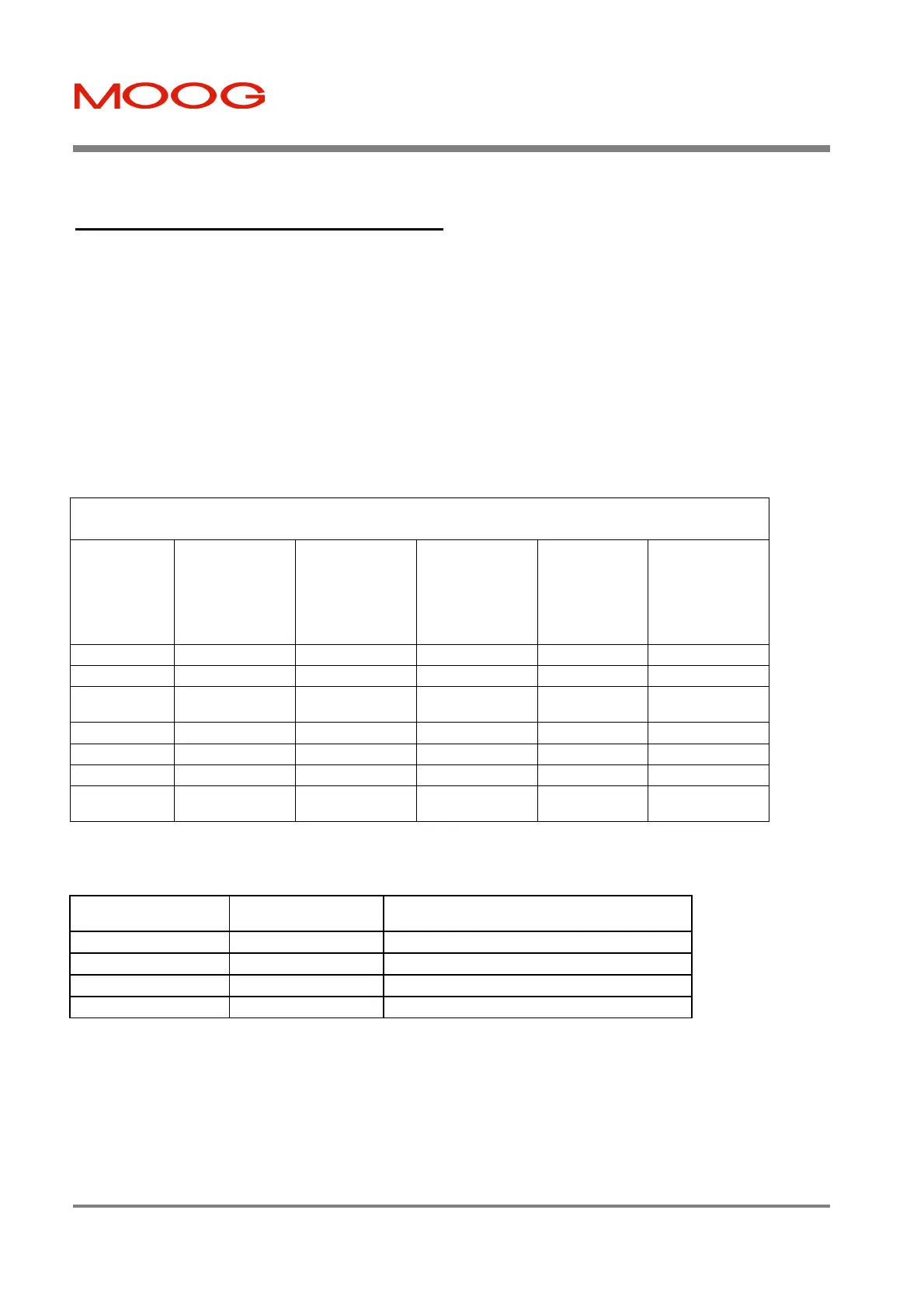
Digital / Relay Outputs (functionality dependent on control mode)
Digital Output
Current/Velocity
Mode
(± 10V Reference,
Digital Speed
Input)
Position Mode
(Custom POINT,
for Simple Point
see spec)
Position Mode
CAN Profile-
Mode
Position Mode
CAN Inter-
polation Mode
Stepper Mode
DO1 (J1/19) Limit Active Limit Active Limit Active Limit Active Limit Active
DO2 (J1/20) Drive Enabled Drive Enabled Drive Enabled Drive Enabled Drive Enabled
DO3 (J1/21)
Speed/Torque
achieved
User defined
Speed/Torque
achieved
User defined
Following Error
exceeded
DO4 (J1/27) Fault Code Bit 1 User defined Undefined User defined Fault Code Bit 1
DO5 (J1/28) Fault Code Bit 2 User defined Undefined User defined Fault Code Bit 2
Relay
(J1/22, J1/23)
System Ready
(relay output)
System Ready
(relay output)
System Ready
(relay output)
System Ready
(relay output)
System Ready
(relay output
Table 6.3 Digital/Relay Outputs (Mode 1)
Digital outputs four and five indicate the following drive status.
Dig. Output DO5
(Fault Code Bit 2)
Dig. Output DO4
(Fault Code Bit 1)
Status of the drive
0 0 Drive ok. No faults
0 1 Motor Fault
1 0 Amplifier Fault
1 1 Limit Switch Active
Table 6.4 Status Indication via DO4 and DO5 (Mode 1)
Note:
0 means a logical 0. I.e. no current flowing.
1 means a logical 1. I.e. current flowing.
Artisan Technology Group - Quality Instrumentation ... Guaranteed | (888) 88-SOURCE | www.artisantg.com

 Loading...


