T200 User's Manual SECTION 3: WIRING AND INSTALLATION
PAGE 3-14
3.2 Equipment Mounting
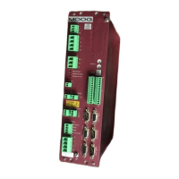
Figures 3.2 to 3.7 show the mechanical dimensions of the T200 chassis, as well as required clearances for cabling etc..
The T200 is designed to be panel or cabinet mounted. The T200 must be mounted in a vertical orientation. The T200
must be panel mounted within an enclosure or cabinet which provides a degree of ingress protection against liquids and
objects of at least IP54. Such enclosures or cabinets must be accessible to technically qualified service or maintenance
persons only. It is recommended that the cabinet be ventilated using filtered or conditioned air, free of corrosive or
electrically conductive contaminants. The accumulation of dust, dirt, etc. on the equipment must be avoided. A
minimum clearance of 40mm above and below the servo-drive is recommended for the T200-3, T200-4 and T200-5
models, and a minimum clearance of 60mm above and below the servo-drive is recommended for the T200-6 and T200-
7 models. If any of the T200 units is mounted in a closed cabinet, allow 60mm clearance at the front.
The T200 must be permanently and reliably connected to Earth and all conductive parts in the IP54 rated enclosure or
cabinet must be permanently connected to Earth. The impedance between the earth terminal and any accessible part of
the enclosure or cabinet should be less than or equal to 0.1 Ω.
NOTE - The T200 Series Servo-drives are system components that must be
installed in the correct manner to ensure that all electromagnetic compatibility
(EMC) requirements are met. (Refer to Section 2 of this User’s Guide).
The T200 must be mounted on a panel with a flat solid surface in a manner
that ensures that EMC earthing requirements are met.
There must be a clean flat conductive surface at all of the mounting points.
Remove paint or other insulating materials and provide conductive corrosion
protection at the mounting points. It is important that there is good high-
frequency bonding between the panel and the T200 Servo-drive. Conductive
hex socket head bolts (metric M5 or Imperial #10) with conductive locking
washers should be used.
Required for
CE-Compliance
Artisan Technology Group - Quality Instrumentation ... Guaranteed | (888) 88-SOURCE | www.artisantg.com

 Loading...