T200 User's Manual SECTION 6: T200 FUNCTIONAL OVERVIEW
PAGE 6-66
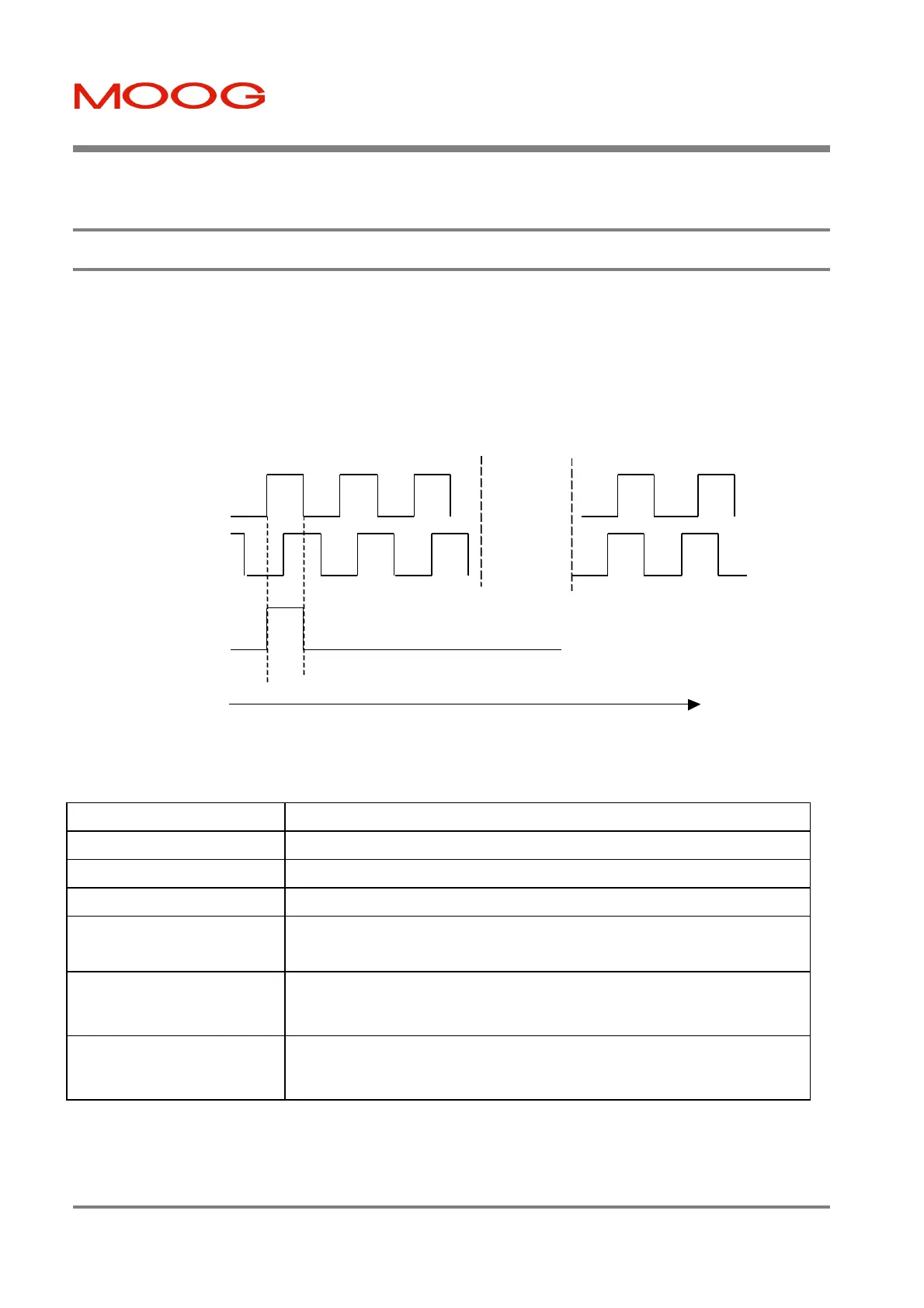
6.11 Incremental Encoder Input
A quadrature incremental encoder input is provided on the T200. This encoder is not used for motor commutation
purposes, but for feedback of relative position information to the Point motion control software or CAN interface
system. The encoder interface accepts Channel A, Channel B and Zero Marker Differential Inputs in RS422 electrical
format. A position latch function is also provided via connector J1, such that the encoder position is latched when the
latch digital input transitions from inactive to active (i.e. current flows in the input).
Figure 6.25:- Quadrature Incremental Encoder Input on J5
Specification Area Specification Description
Maximum Line Frequency Up to 1MHz Line Frequency (i.e. 4MHz edge frequency)
Input Voltage Range Input Line Voltages are RS422 compatible.
Channel Input Impedances Encoder Input is terminated with 120Ohms impedance
Encoder Fault Detection The following faults are detectable:-
Disconnected encoder lines (via monitoring of encoder voltages)
Position Registration Latch The Position Registration Latch input is provided as a means of latching position
upon detection of an event. The encoder position is latched within 1us of the
inactive to active transition of this input.
Voltage Supply for Encoder The T200 provides a 5V non-isolated supply for an external encoder. Note that
an internal resetable fuse in series with the output will provide protection in the
event that the external encoder device goes short circuit.
Table 6.7:- Incremental Encoder Input Specification
Increasing Encoder Position
ENC_A
ENC_B
ENC_MARKER
Clockwise Counter-Clockwise
A leads B B leads A
Artisan Technology Group - Quality Instrumentation ... Guaranteed | (888) 88-SOURCE | www.artisantg.com

 Loading...


