T200 User's Manual SECTION 7: WINDRIVE
PAGE 7-40
7.10.1.7 Drive Tuning
This dialog enables the user to select the Control Mode for the drive, set up the Tuning Gains as well as enter additional
tuning related dialogs. Refer to section 7.11.1 Control Mode Selection.
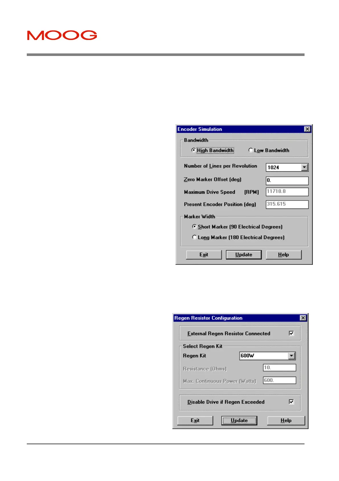
7.10.1.8 Encoder Simulation (ESM)
The functionality of an incremental rotary encoder may be
emulated with Encoder Simulation software. Feedback
information is read from the motor resolver where it is
interpreted by a software/hardware model (depending on ESM
mode) and converted into Encoder Simulation information.
The user must enter a value for the Number of Lines per
Revolution. Two modes of Encoder Simulation are available,
High Bandwith and Low Bandwith.
1. High Bandwidth ('ESM3'): This is recommended for
use when the T200 is placed in Torque Mode. This uses
an analog hardware solution for the Encoder Simulation,
but only values of 128, 256, 512 or 1024 may be used for
the Number of Lines per Revolution. A position
feedback bandwidth of between 800 and 1000 Hz is
available when High Bandwidth mode is used.
2. Low Bandwidth (ESM1): This is recommended for use
when the T200 is placed in Velocity Mode. Any other
even number between 128 and 8192 entered for the
Number of Lines per Revolution will result in Low
Bandwidth operation. A hybrid of software and
hardware, the feedback bandwidth of Low Bandwidth
mode is limited to 400 Hz.
Figure 7.43: Encoder Simulation Dialog Box
The user may determine the Zero Marker Offset in mechanical motor shaft degrees of the zero marker of the Encoder
Simulation output, with respect to the motor’s own resolver position sensor natural zero position. Both the Maximum
Drive Speed and Present Encoder Position fields are determined by the software and system parameters. The Marker
Width options are selectable from Short Marker (90 Electrical Degrees) and Long Marker (180 Electrical Degrees).
7.10.1.9 Regen (Brake) Resistor Configuration
The Regen Resistor Configuration dialog box allows the user
to set up the selected regen (regeneration) resistor. The
correct parameters for the regen resistor are essential for a
proper operation of the Regen Exceeded functionality as
described in section 6.8.5.
External Regen Resistor Connected: Enables the Regen
Exceeded functionality which indicates that the maximum
continuous power of the external regen resistor is exceeded.
This box needs to be ticked if an external regen resistor is
connected to the T200.
Disable Drive if Regen Exceeded: If this box is ticked the
T200 will perform a Quick Stop and disable as soon as the
maximum continuous regen power is exceeded. Otherwise
only regen exceeded will be indicated but no Quick Stop is
performed. For further description see section 6.8.5.
Artisan Technology Group - Quality Instrumentation ... Guaranteed | (888) 88-SOURCE | www.artisantg.com

 Loading...


