SECTION 6: T200 FUNCTIONAL OVERVIEW T200 User's Manual
PAGE 6-69
6.12.2 Following Error Detection
Indication and reaction of the drive when the Following Error Limit is exceeded
The “Speed/Torque Achieved” output (SPD/TORQ_ACHVD pin 21 of J1), is used to indicate to the user that the
Following Error Limit is exceeded. As soon as the Following Error Limit is exceeded the SPD/TORQ_ACHVD output
will be turned on. The SPD/TORQ_ACHVD output will stay turned on until the drive is disabled. The Following Error
will be clamped to the Following Error Limit.
The 7-segment display will display “E4” if the Following Error Limit is exceeded.”E4” is ba sed on the actual Following
Error. I.e. if the drive catches up with the stepper pulses “E4” will no longer be displayed even when the
SPD/TORQ_ACHVD output is still switched on.
If the Following Error Limit function is disabled (parameter set to 819200) the max. following error will be clamped to
50revs but there will be no user indication. Neither the SPD/TORQ_ACHVD output will be set nor “E4” will be
displayed.
Setting of the Following Error Limit parameter
The max. allowed Following Error can be set up via the Dynamic Error (incs) in the WinDrive “Tracking Monitoring”
window or via the POD command “SFFE”/”LFFE”.The Following Error Limit need to be set up in increments. One
motor revolution equals 16384 increments.
The parameter range is from 1024incs up to 819200incs. Any value beyond this range will cause a parameter error. The
default value is 819199 increments (49.99 revolutions). The value of 819200 increments (50 revolutions) disables the
Following Error Limit feature.
The Static Error does not apply. In WinDrive the Static Error will be greyed out if the drive is in Stepper Mode.
If in Stepper Mode the Drive Status Window displays “Following Error Exceeded” instead of “Speed/Torque Achieved”
(“Set Point Achieved”).
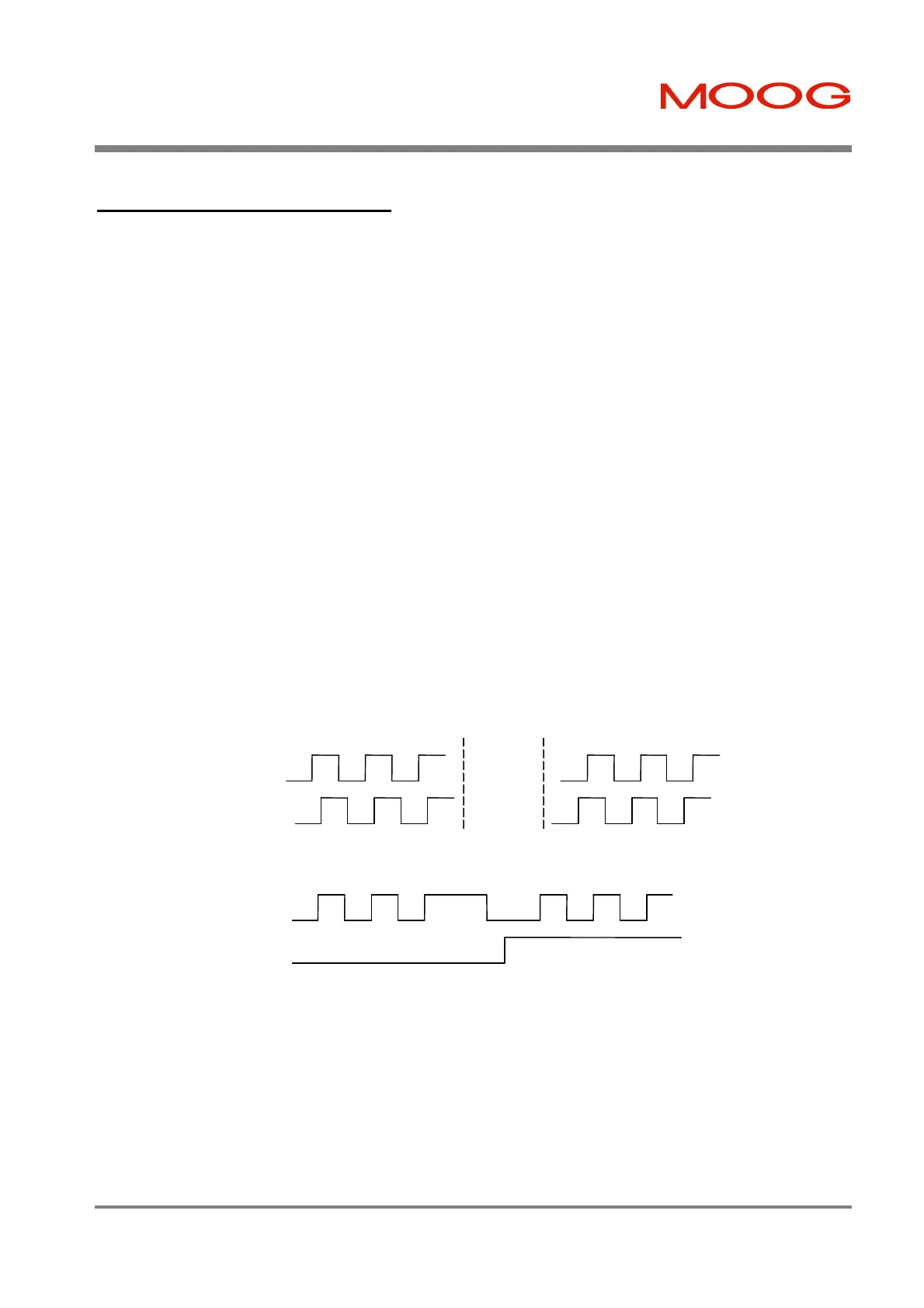
Figure 6.27:- Stepper Motor Interface Mode Signals on Connector J5
Clockwise (A leads B) Counterclockwise (B leads A)
ENC_A
ENC_B
a) Quadrature
ENC_A
ENC_B
b) Step and Direction
Artisan Technology Group - Quality Instrumentation ... Guaranteed | (888) 88-SOURCE | www.artisantg.com

 Loading...


