T200 User's Manual SECTION 6: T200 FUNCTIONAL OVERVIEW
PAGE 6-40
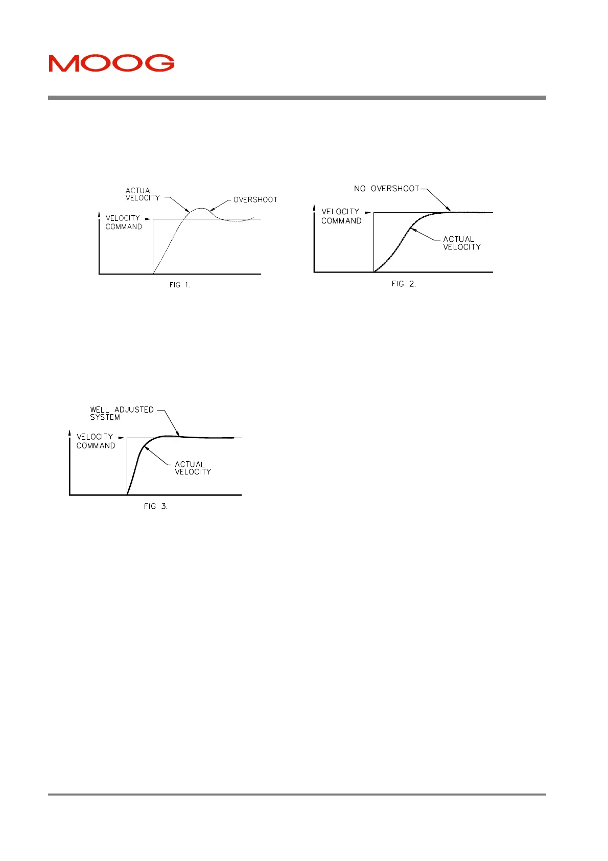
• Use the P command set to enter the gain adjust mode for the velocity loop proportional gain term. Using the PU
command increase the P gain until the shaft is turning. Use the PU command, while monitoring the velocity
response on the oscilloscope, to increase the P gain until a slight overshoot occurs in the velocity response (Fig 1
below). Use the PD command to decrease the P gain until the overshoot just disappears (Fig 2 below) .
• Use the I command set to enter the gain adjust mode for the velocity loop integral time constant. Using the IU
command increase the loop response (this will actually reduce the Integral Time Constant) until a slight overshoot
occurs again .
• Use the P command set to re-enter the P gain adjust mode. Use the PU command to improve the slope of the step
response. Fig 3 illustrates the velocity wave form for a properly tuned loop.
6.7.2.9 Velocity Observer Tuning and Usage
This Section explains the set-up and tuning of the velocity observer. The use of the observer will usually allow
significantly higher velocity loop gains and bandwidths to be achieved. The observer uses a software model of the
motor and load to calculate a velocity estimate. The user needs to tune only one additional parameter to use the
observer. The observer is set up using the following procedure:
• Tune the velocity loop using the normal procedure described in Section 6.6.2.8 . Figure 6.20 (A) below shows a
typical tuned velocity loop response to a step reference command. It shows the torque response on the drives' TP1
test point and the actual velocity response on TP2. The size of the step velocity reference should be small enough to
avoid saturation of the torque signal. Note the single overshoot of about 24% in the velocity response and the 12 ms
settling time.
• Tune the observer by setting up the observer inertia parameter, Jest. Monitor the observer error signal θerr at the
drives' TP1 test point (see Section 6.4.3 TP1 Analog Output and Section 8 for a description of the Hand Held
terminal interface). Figure (B) shows the usual starting point for tuning: J
est
is too small. Use the JU command to
enter the gain adjust mode, (refer to Section 8 for an outline of hand held terminal commands). J
est
may be
adjusted in this mode using JU and/or JD commands, or using the SJ / LJ commands,(refer to Section 8). Figure
Artisan Technology Group - Quality Instrumentation ... Guaranteed | (888) 88-SOURCE | www.artisantg.com

 Loading...


