APPENDIX A: EMC TEST CONFIGURATION T200 User's Manual
PAGE A-9
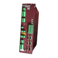
Both Drives were mounted onto an earthed metal panel mounted in turn onto an earthed equipment chassis frame. The
bare metal rear panel of each Drive enclosure was fixed in direct contact with the earthed metal panel on the equipment
chassis.
Output cables were grouped and routed along the chassis of the equipment frame in a manner similar to routing of cables
on machinery. The motor power and motor resolver cables were grouped together and installed in a fixed routing to the
motors. The output port cables, motor power and resolver cables, and power input cables had segregated routings.
Single Phase Power Application: Line Filtering (Models T200-3XX, -4XX, -5XX).
An a.c. power input Line Filter is required to be installed by the user in the a.c. power input supply lines. The following
power input Line Filter is recommended:
Type: FN 350-12-29, manufactured by Schaffner, Switzerland. ( Rated 12 A r.m.s.)
Care must be taken when installing the a.c. power input Line Filter to ensure that the ability of the filter to function
effectively is not degraded.
When installing the Line Filter, care must be taken to implement the following measures:
• Install the Line Filter on an earthed metal panel. There must be continuous earth continuity with good HF
bonding between this panel and the panel on which the T200 Series Controllers are mounted. This must result in
continuous earth continuity with good HF bonding between the enclosure of the Line Filter and the enclosures of
the T200 Series Controllers.
• Remove paint or other insulating materials and provide conductive corrosion protection at the mounting points
for the Line Filter. Secure the filter using conductive bolts and locking washers.
• Locate the Line filter as close as possible to the T200 Power input connector. Total cable length from Line Filter
to the T200 Power input connector should not exceed 1 metre. Keep all cable lengths as short as possible and
route separately from other cables and conductors.
• If using shielded or armoured cable for all connections from Line Filter to the T200 Power input connector, the
shields of these voltage supply cables should be earthed to Chassis Earth using a 180 degree metal clamp (P clip)
connection. Alternatively, if the cable is required to pass through an enclosure panel earthed to Chassis Earth, the
shield may be earthed to the panel by use of a 360 degree metal cable gland.
• Ensure that the Line Filter is firmly connected to mains Earth and that the Protective Earth (PE) of the Line Filter
is correctly connected to the Protective Earth (PE) of the T200 Series Controllers. Ensure that there is good high-
frequency (HF)bonding between enclosure of the Line Filter, T200 Series Controllers and Protective Earth (PE).
• Ensure that input and output cables from the Line Filter are segregated as much as possible to prevent noise
coupling. ( See figures below ). It is essential that the input conductors to the Line Filter be completely
segregated from both the filter output conductors and all other cables and conductors in the installed product.
Artisan Technology Group - Quality Instrumentation ... Guaranteed | (888) 88-SOURCE | www.artisantg.com

 Loading...