T200 User's Manual SECTION 6: T200 FUNCTIONAL OVERVIEW
PAGE 6-68
6.12 Stepper Motor Interface
In Stepper Motor Inerface Mode the T200 can be used to replace a stepper motor if the dynamics of the stepper motor do
not satisfy the requirements of the application. This mode allows as well an easy implementaiton of an electronic
gearing. In Stepper Motor Interface Mode the T200 operates in Position Mode. This means that the Position Loop needs
to be tuned for proper operation. Tuning of the Position Loop is described in Section 6.6.3. Setup with the WinDrive
Graphical User Interface is described in Section 7.10.1.3.
In Quadrature Mode, the edges of ENC_A and ENC_B will generate a movement of ¼ of a step, i.e. each edge is 1
count. The relative phase of ENC_A and ENC_B will determine direction. For example, if the number of steps is 1024
and a 1024 line encoder is attached, then the motor shaft will turn 1 rev for 1 revolution of the encoder. The motor
rotation is clockwise viewed from the motor flange when ENC_A leads ENC_B.
In Step and Direction Mode, ENC_A is used to trigger a step for each pulse on ENC_A, ENC_B is used to determine
direction. When ENC_B+ is low and ENC_B- is high, the motor rotation is clockwise viewed from the motor flange. For
counter-clockwise rotation, ENC_B+ must be high and ENC_B- must be low.
.
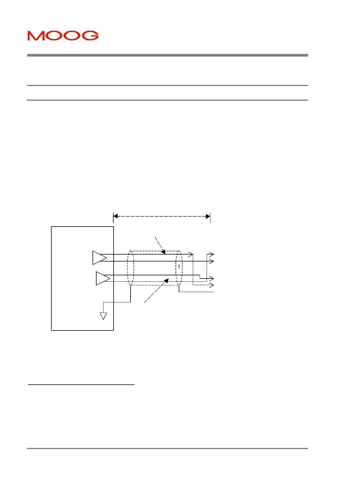
Figure 6.26:- Stepper Motor Interface Interconnect
If the T200 is in Stepper Mode the additional functionality is supported:
6.12.1 Hardware Limit Switches
If the drive is in Stepper Mode the HW Limit Switches can be enabled or disabled via the Hand-Held-Terminal
command “OL” or via the “Limit Switch”-Window in WinDrive.
If a Limit Switch is hit and Limit Switches are enabled the drive ramps down to 0rpm in Position Mode with the
Emergency Deceleration Rate and stays enabled. Further movements in the direction where the Limit Switch is hit are
not possible. Movements in the other direction are possible.
User Control
System
J5
DGND
ENC_MARkER-
ENC_B-
ENC_A-
ENC_VCC
ENC_MARKER+
ENC_B+
ENC_A+
PE
1
2
3
4
5
6
7
8
9
20m max
0.5sq.mm
twisted pair
O/P
Line
Driver
Channel A Pair
O/P
Line
Driver
Channel B Pair
Artisan Technology Group - Quality Instrumentation ... Guaranteed | (888) 88-SOURCE | www.artisantg.com

 Loading...


