Zynq-7000 AP SoC and 7 Series FPGAs MIS v4.1 290
UG586 November 30, 2016
www.xilinx.com
Chapter 2: QDR II+ Memory Interface Solution
• Latency Mode – If fixed latency through the core is needed, the Fixed Latency Mode
option allows you to select the desired latency. This option can be used if the user
design needs a read response returned in a predictable number of clock cycles. To use
this mode, select the Fixed Latency Mode box. After enabling fixed latency, the
pull-down box allows you to select the number of cycles until the read response is
returned to you. This value ranges from 21 to 30 cycles. Based on actual hardware
conditions, if the latency seen through the system is higher, you need to modify this
value accordingly in the top-level RTL file.
When Fixed Latency Mode is enabled, failures can occur if the actual read latency is
larger than the specified Fixed Latency value. Read Latency can vary across byte lanes
by as much as five clock cycles because of the command output path in the PHY control
block and data input path across asynchronous IN_FIFO.
Note:
Xilinx recommends adding five additional clocks to the minimum latency measured to
determine the actual fixed latency value to be used. If Fixed Latency Mode is not used, the core
uses the minimum number of cycles through the system.
• Memory Details – The bottom of the Controller Options page. Figure 2-18 displays
the details for the selected memory configuration.
Create Custom Part
1. On the Controller Options page select the appropriate frequency. Either use the spin
box or enter a valid value using the keyboard. Values entered are restricted based on the
minimum and maximum frequencies supported.
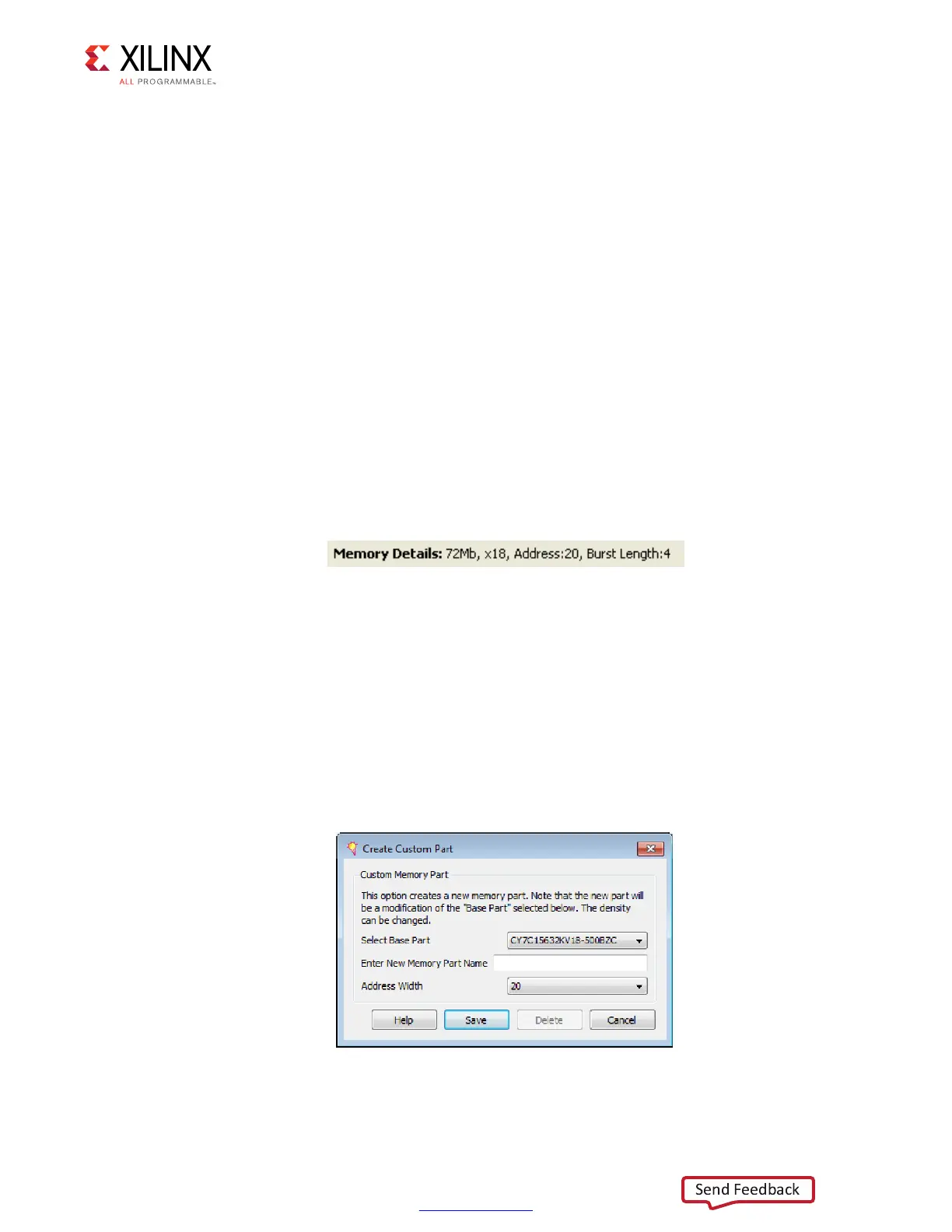
2. Select the appropriate Memory Part from the list. If the required part or its equivalent
is unavailable, a new memory part can be created. To create a custom part, click the
Create Custom Part below the Memory Part pull-down menu. A new page appears, as
shown in Figure 2-19.
X-Ref Target - Figure 2-18
Figure 2-18: Selected Memory Configuration Details
X-Ref Target - Figure 2-19
Figure 2-19: Create Custom Part Page
 Loading...


