Zynq-7000 AP SoC and 7 Series FPGAs MIS v4.1 324
UG586 November 30, 2016
www.xilinx.com
Chapter 2: QDR II+ Memory Interface Solution
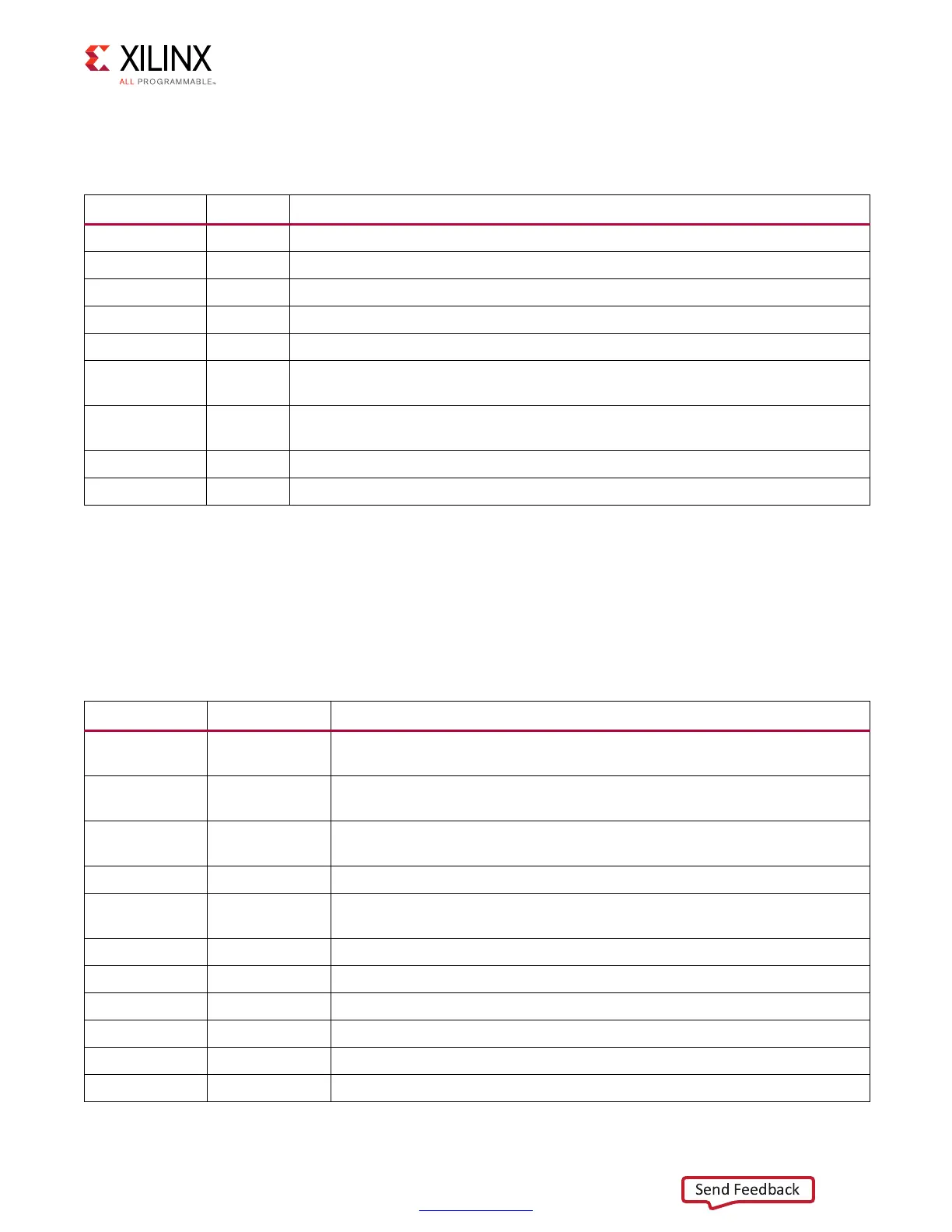
Table 2-8 lists the signals used in the infrastructure module that provides the necessary
clocks and reset signals required in the design.
Physical Interface
The physical interface is the connection from the FPGA memory interface solution to an
external QDR II+ SRAM device. The I/O signals for this interface are shown in Table 2-9.
These signals can be directly connected to the corresponding signals on the QDR II+ SRAM
device.
Table 2-8: Infrastructure Clocking and Reset Signals
Signal Direction Description
mmcm_clk Input System clock input.
sys_rst Input Core reset from user application.
iodelay_ctrl_rdy Input IDELAYCTRL lock status.
clk Output Half frequency FPGA logic clock.
mem_refclk Output PLL output clock at same frequency as the memory clock.
freq_refclk Output
PLL output clock to provide the FREQREFCLK input to the Phaser. The freq_refclk is
generated such that its frequency in the range of 400 MHz to 1,066 MHz.
sync_pulse Output
PLL output generated at 1/16 of mem_Refclk and is a synchronization signal sent
to the PHY hard blocks that are used in a multi-bank implementation.
pll_locked Output Locked output from PLLE2_ADV.
rstdiv0 Output Reset output synchronized to internal FPGA logic half frequency clock.
Table 2-9: Physical Interface Signals
Signal Direction Description
qdr_cq_n Input
QDR CQ#. This is the echo clock returned from the memory derived from
qdr_k_n.
qdr_cq_p Input
QDR CQ. This is the echo clock returned from the memory derived from
qdr_k_p.
qdr_d Output
QDR Data. This is the write data from the PHY to the
QDR II+ memory
device.
qdr_dll_off_n Output QDR DLL Off. This signal turns off the DLL in the memory device.
qdr_bw_n Output
QDR Byte Write. This is the byte write signal from the PHY to the QDR II+
SRAM device.
qdr_k_n InOut QDR Clock K#. This is the inverted input clock to the memory device.
qdr_k_p InOut QDR Clock K. This is the input clock to the memory device.
qdr_q Input QDR Data Q. This is the data returned from reads to memory.
qdr_sa Output QDR Address. This is the address supplied for memory operations.
qdr_w_n Output QDR Write. This is the write command to memory.
qdr_r_n Output QDR Read. This is the read command to memory.