Zynq-7000 AP SoC and 7 Series FPGAs MIS v4.1 596
UG586 November 30, 2016
www.xilinx.com
Chapter 4: LPDDR2 SDRAM Memory Interface Solution
PHY Control Block
The PHY control block is the central block that manages the flow of data and control
information between the FPGA logic and the dedicated PHY. This includes control over the
flow of address, command, and data between the IN/OUT_FIFOs and ISERDES/OSERDES,
and control of the PHASER_IN and PHASER_OUT blocks. The PHY control block receives
control words from the calibration logic or the Memory Controller at the slow frequency
(1/2 the frequency of the LPDDR2 SDRAM clock) PHY_Clk rate and processes the control
words at the LPDDR2 SDRAM clock rate (CK frequency).
The calibration logic or the Memory Controller initiates a LPDDR2 SDRAM command
sequence by writing address, command, and data (for write commands) into the
IN/OUT_FIFOs and simultaneously or subsequently writes the PHY control word to the PHY
control block. The PHY control word defines a set of actions that the PHY control block does
to initiate the execution of a LPDDR2 SDRAM command.
The PHY control block provides the control interfaces to the byte group blocks within its I/O
bank. When multi-I/O bank implementations are required, each PHY control block within a
given I/O bank controls the byte group elements in that bank. This requires that the PHY
control blocks stay in phase with their adjacent PHY control blocks. The center PHY control
block is configured to be the master controller for a three I/O bank implementation. For two
bank implementations, either PHY control block can be designated the master.
The PHY control interface is used by the calibration logic or the Memory Controller to write
PHY control words to the PHY. The signals in this interface are synchronous to the PHY_Clk
and are listed in Table 4-21. This is a basic FIFO style interface. Control words are written
into the control word FIFO on the rising edge of PHY_Clk when PHY_Ctl_WrEn is High and
PHY_Ctl_Full is Low. For multi-I/O bank PHYs, the same control word must be written
into each PHY control block for proper operation.
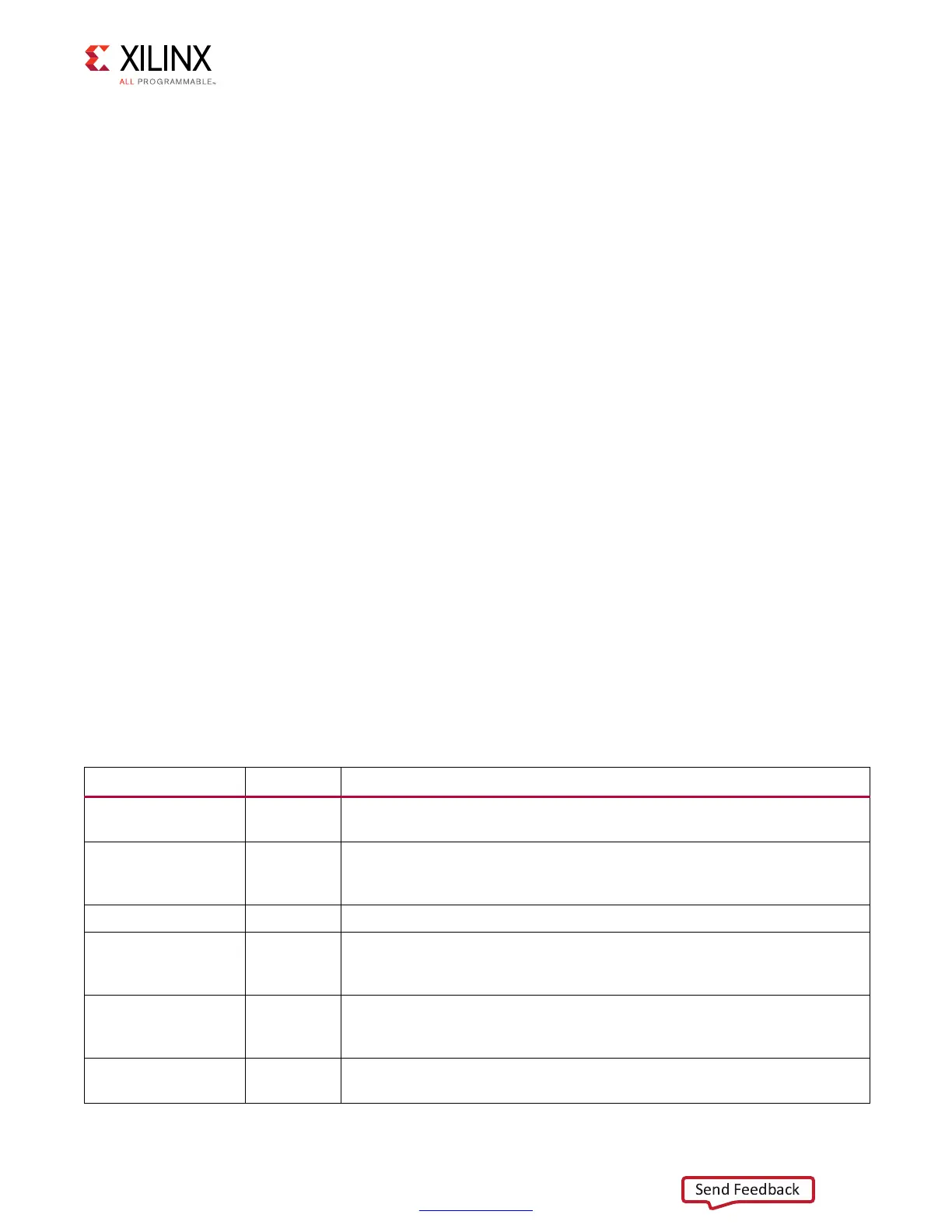
Table 4-21: PHY Control Interface
Signal Direction Description
PHY_Clk Input
This is the PHY interface clock for the control word FIFO. PHY control word
signals are captured on the rising edge of this clock.
PHY_Ctl_Wr_N Input
This active-Low signal is the write enable signal for the control word FIFO.
A control word is written into the control word FIFO on the rising edge of
PHY_Clk, when this signal is active.
PHY_Ctl_Wd[31:0] Input This is the PHY control word described in Table 4-22.
PHY_Ctl_Full Output
This active-High output is the full flag for the control word FIFO. It indicates
that the FIFO cannot accept anymore control words and blocks writes to the
control word FIFO.
PHY_Ctl_AlmostFull Output
This active-High output is the almost full flag for the control word FIFO. It
indicates that the FIFO can accept no more than one additional control
word as long as the PHY_Ctl_Full signal is inactive.
PHY_Ctl_Ready Output
This active-High output becomes set when the PHY control block is ready
to start receiving commands.
 Loading...


