Zynq-7000 AP SoC and 7 Series FPGAs MIS v4.1 618
UG586 November 30, 2016
www.xilinx.com
Chapter 4: LPDDR2 SDRAM Memory Interface Solution
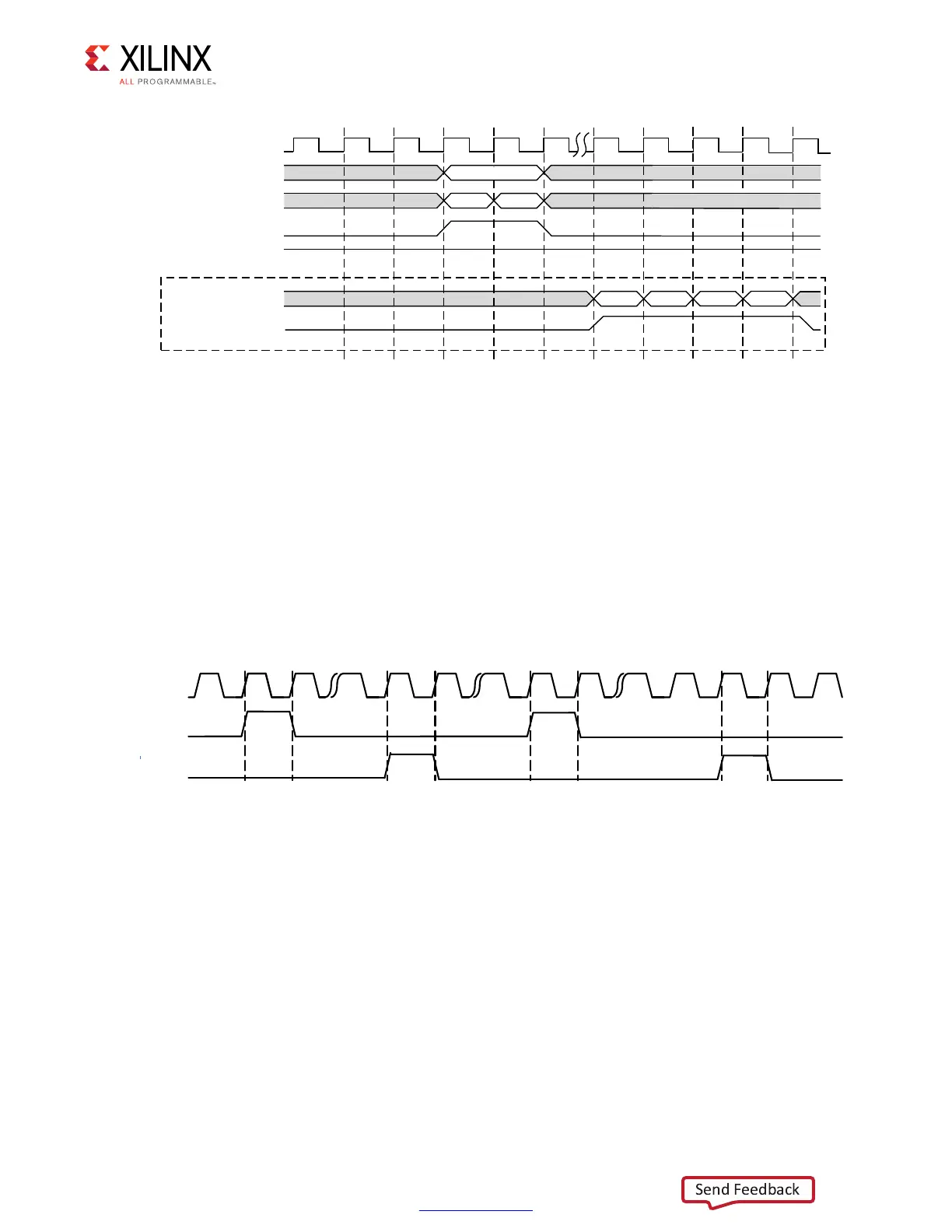
In Figure 4-65, the read data returned is always in the same order as the requests made on
the address/control bus.
User ZQ
For user-controlled ZQ calibration, the Memory Controller managed maintenance should
be disabled by setting the tZQI parameter to 0.
To request a ZQ command, app_zq_req is strobed for one cycle. When the Memory
Controller sends the command to the PHY, it strobes app_zq_ack for one cycle, after
which another request can be sent. Figure 4-66 illustrates the interface.
A user ZQ operation can be performed any time provided the handshake defined above is
followed. There are no additional interfacing requirements with respect to other commands.
However, pending requests affect when the operation goes out. The Memory Controller
fulfills all pending data requests before issuing the ZQ command.
Timing parameters must be considered for each pending request when determining when
to strobe app_zq_req to achieve the desired interval if precision timing is desired. To
account for the worst case, subtract tRCD, CL, the data transit time and tRP for each bank
machine to ensure that all transactions can complete before the target tZQI expires.
Equation 4-1 shows the ZQ request interval maximum.
Equation 4-1
X-Ref Target - Figure 4-65
Figure 4-65: UI Interface Read Timing Diagram (Memory Burst Type = BL4 or BL8)
DSSBUGBGDWD
FON
DSSBFPG
5D
DSSBDGGU
$GGUE
DSSBHQ
DSSBUGBGDWDBYDOLG
DSSBUG\
$GGUD
5D
5($'
5E 5E
X-Ref Target - Figure 4-66
Figure 4-66: User ZQ Interface
CLK
APP?ZQ?REQ
APP?ZQ?ACK
8
tZQI tRCD CL 4+()tCK×()+ tRP+()nBANK_MACHS×–()
 Loading...


