Zynq-7000 AP SoC and 7 Series FPGAs MIS v4.1 410
UG586 November 30, 2016
www.xilinx.com
Chapter 3: RLDRAM II and RLDRAM 3 Memory Interface Solutions
Directory Structure and File Descriptions
This section explains the MIG tool directory structure and provides detailed output file
descriptions.
Output Directory Structure
The MIG tool places all output files and directories in a folder called <component name>,
where <component name> was specified on the MIG Output Options, page 388 of the MIG
design creation flow.
The output directory structure of the selected Memory Controller (MC) design from the MIG
tool is shown here There are three folders created within the <component name>
directory:
• docs
• example_design
• user_design
X-Ref Target - Figure 3-34
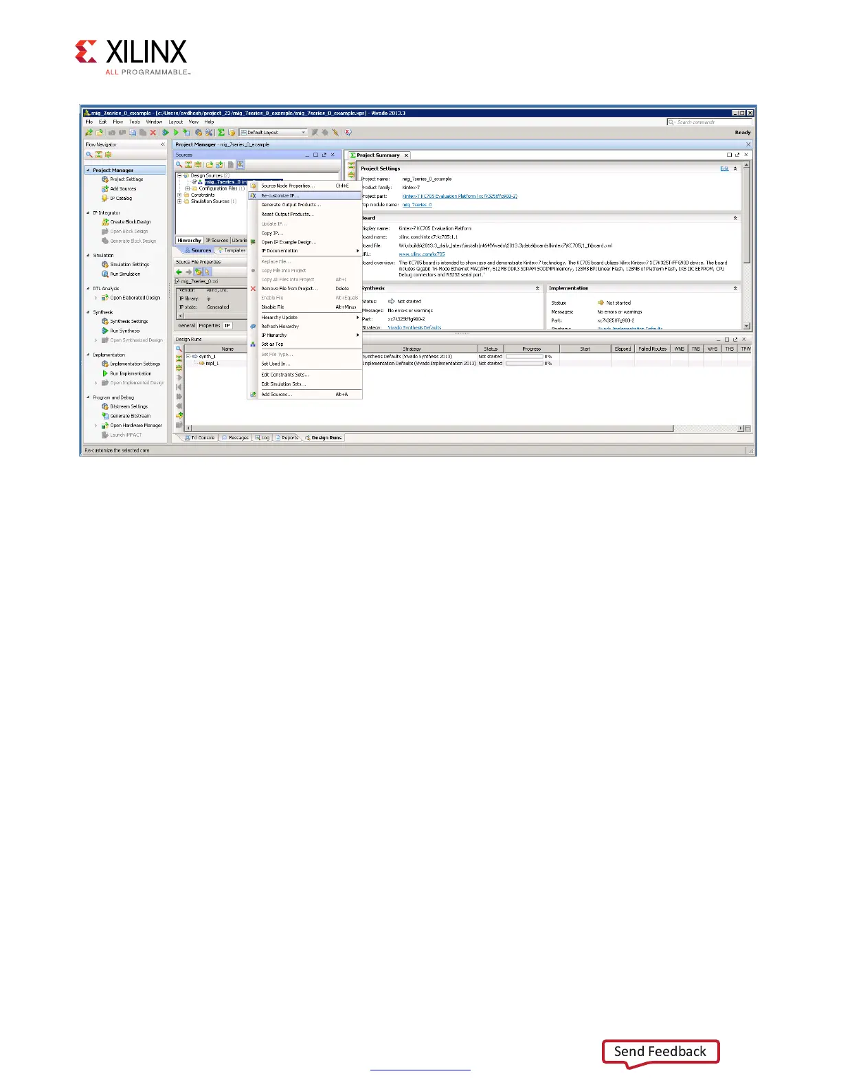
Figure 3-34: Recustomize IP
 Loading...


