Zynq-7000 AP SoC and 7 Series FPGAs MIS v4.1 363
UG586 November 30, 2016
www.xilinx.com
Chapter 2: QDR II+ Memory Interface Solution
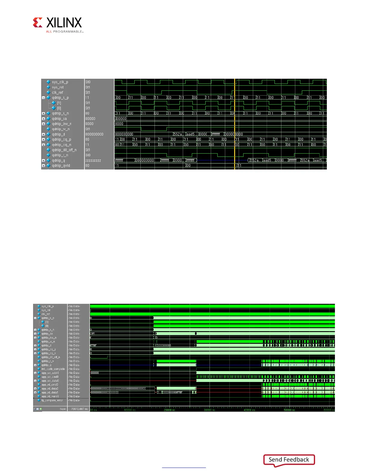
The second stage performs a read enable calibration. The data pattern used during this
stage is ..55..AA. The data pattern is first written to the memory, and then read back for the
read enable calibration, as shown in Figure 2-57.
An additional read is performed so the read bus is driven to a different value. This is mostly
required in hardware to make sure that the read calibration can distinguish the correct data
pattern.
After second stage calibration completes, cal_done is asserted, signifying successful
completion of the calibration process.
Test Bench
After cal_done is asserted, the test bench takes control, writing to and reading from the
memory. The data written is compared to the data read back. Any mismatches trigger an
assertion of the error signal. Figure 2-58 shows a successful implementation of the test
bench with no assertions on error.
X-Ref Target - Figure 2-57
Figure 2-57: Write and Read for Second Stage Read Calibration
X-Ref Target - Figure 2-58
Figure 2-58: Test Bench Operation After Completion of Calibration
 Loading...


