Zynq-7000 AP SoC and 7 Series FPGAs MIS v4.1 333
UG586 November 30, 2016
www.xilinx.com
Chapter 2: QDR II+ Memory Interface Solution
Calibration
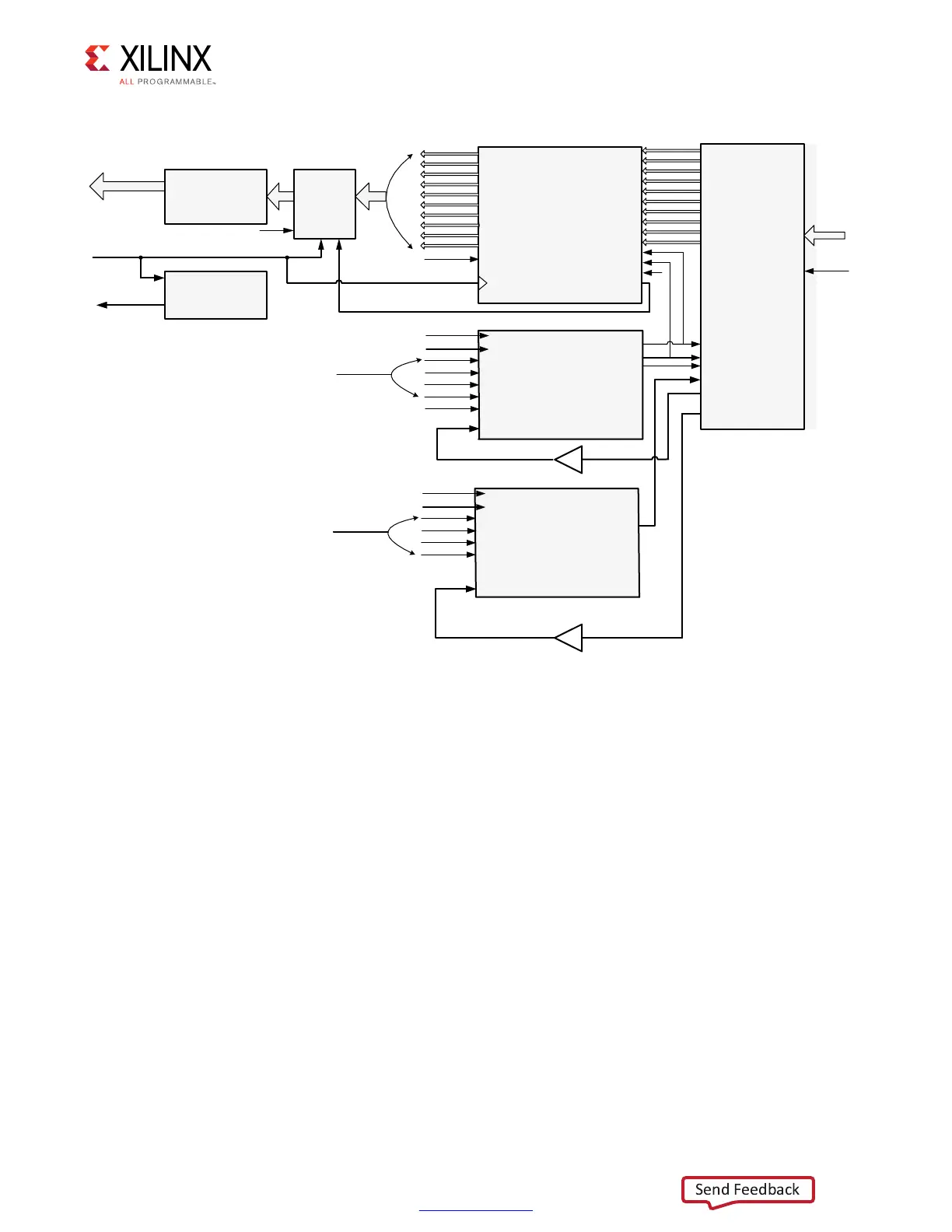
The calibration logic provides the required amount of delay on the read clock and read data
to align the clock in the center of the data valid window. The centering of the clock is done
using PHASERs which provide very fine resolution delay taps on the clock. Each PHASER_IN
fine delay tap increments the clock by 1/64
th
of the data period.
Calibration begins after the echo clocks are stable from the memory device. The amount of
time required to wait for the echo clocks to become stable is based upon the memory
vendor and should be specified using the CLK_STABLE parameter to the core. Prior to this
point, all read path logic is held in reset. Calibration is performed in two stages:
1. Calibration of read clock with respect to Q
2. Data alignment and valid generation
X-Ref Target - Figure 2-46
Figure 2-46: Read Datapath
).?&)&/
$;=
234
2$#,+
72#,+
72%.
%-049
$;=
$;=
$;=
$;=
$;=
$;=
$;=
$;=
$;=
&2%
1""
2$%.
1;=
1;=
1;=
1;=
1;=
1;=
1;=
1;=
1;=
1;=
-%-2%&#,+
&2%12%&#,+
&).%%.!",%
&).%).#
#/5.4%2,/!$%.
#/5.4%2,/!$6!,
)#,+$)6
)#,+
)3%2$%3234
),/')#
)3%2$%3
)$%,!9
1;=
)3%2$%3OUTPUTDATA
FROMAREADBYTEGROUP
0HY ?CLK
)F?EMPTY
&2%1""
0(!3%2%&#,+
$ELAYCONTROLSFROM
FABRICCALIBRATIONLOGIC
TOPROVIDEREADCLOCKTO
DATACENTERING
0(!3%2?).
%$'%?!$6
&ABRICCONTROLTO
ENSUREREADDATAFROM
)3%2$%3ISALIGNEDTO
0(!3%2?).)#,+$)6
$ATA!LIGNMENT
ACROSSVARIOUSREAD
BYTEGROUPS
6ALIDSIGNAL
GENERATOR
&ABRIC
0(9?#,+
2EADDATA
TOTHEUSER
2EADVALID
SIGNAL
2EAD$ATAFROM
MEMORY
"5&-2
#1#1CLOCKS
FROMMEMORY
0/34?&)&/
$
1
#,+
2$%.
0HY?RD?EN
-%-2%&#,+
&2%12%&#,+
&).%%.!",%
&).%).#
#/5.4%2,/!$%.
#/5.4%2,/!$6!,
/#,+$)6
/#,+
)3%2$%3234
0(!3%2%&#,+
$ELAYCONTROLSFROM
FABRICCALIBRATIONLOGIC
TOPROVIDEREADCLOCKTO
DATACENTERING
0(!3%2?/54
%$'%?!$6
&2%1""
"5&-2
#1
#1
#,+$)6
#,+
#,+"
234
5'?C??
 Loading...


