Zynq-7000 AP SoC and 7 Series FPGAs MIS v4.1 549
UG586 November 30, 2016
www.xilinx.com
Chapter 4: LPDDR2 SDRAM Memory Interface Solution
example_design/rtl/traffic_gen
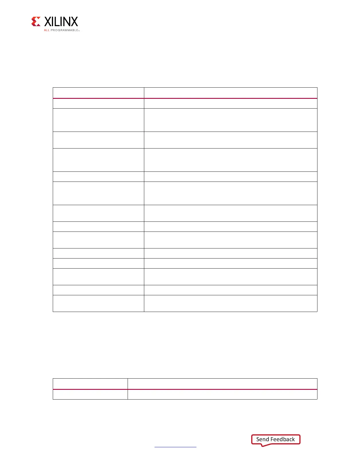
This directory contains the traffic generator that provides the stimulus to the
7 series FPGAs Memory Controller (Table 4-2).
<component name>/example_design/par
Table 4-3 lists the modules in the example_design/par directory.
Table 4-2: Files in example_design/rtl/traffic_gen Directory
Name
(1)
Description
memc_traffic_gen.v This is the top-level of the traffic generator.
cmd_gen.v
This is the command generator. This module provides independent
control of generating the types of commands, addresses, and burst
lengths.
cmd_prbs_gen.v
This is a pseudo-random binary sequence (PRBS) generator for
generating PRBS commands, addresses, and burst lengths.
memc_flow_vcontrol.v
This module generates flow control logic between the Memory
Controller core and the cmd_gen, read_data_path, and
write_data_path modules.
read_data_path.v This is the top-level for the read datapath.
read_posted_fifo.v
This module stores the read command that is sent to the Memory
Controller, and its FIFO output is used to generate expect data for
read data comparisons.
rd_data_gen.v
This module generates timing control for reads and ready signals
to memc_flow_vcontrol.v.
write_data_path.v This is the top-level for the write datapath.
wr_data_g.v
This module generates timing control for writes and ready signals
to memc_flow_vcontrol.v.
s7ven_data_gen.v This module generates different data patterns.
a_fifo.v This is a synchronous FIFO using LUT RAMs.
data_prbs_gen.v
This is a 32-bit linear feedback shift register (LFSR) for generating
PRBS data patterns.
init_mem_pattern_ctr.v This module generates flow control logic for the traffic generator.
traffic_gen_top.v
This module is the top-level of the traffic generator and comprises
the memc_traffic_gen and init_mem_pattern_ctr modules.
Notes:
1. All file names are prefixed with the MIG version number. For example, the MIG 4.1 release module name of
cmd_gen in generated output is now mig_7series_v4_1_cmd_gen.
Table 4-3: Files in example_design/par Directory
Name Description
example_top.xdc This is the XDC for the core and the example design.