Zynq-7000 AP SoC and 7 Series FPGAs MIS v4.1 442
UG586 November 30, 2016
www.xilinx.com
Chapter 3: RLDRAM II and RLDRAM 3 Memory Interface Solutions
Note: The overall read latency of the MIG 7 series RLDRAM II/RLDRAM 3 core is dependent on how
the Memory Controller is configured, but most critically on the target traffic/access pattern and the
number of commands already in the pipeline before the read command is issued. Read latency is
measured from the point where the read command is accepted by the user or native interface.
Simulation should be run to analyze read latency.
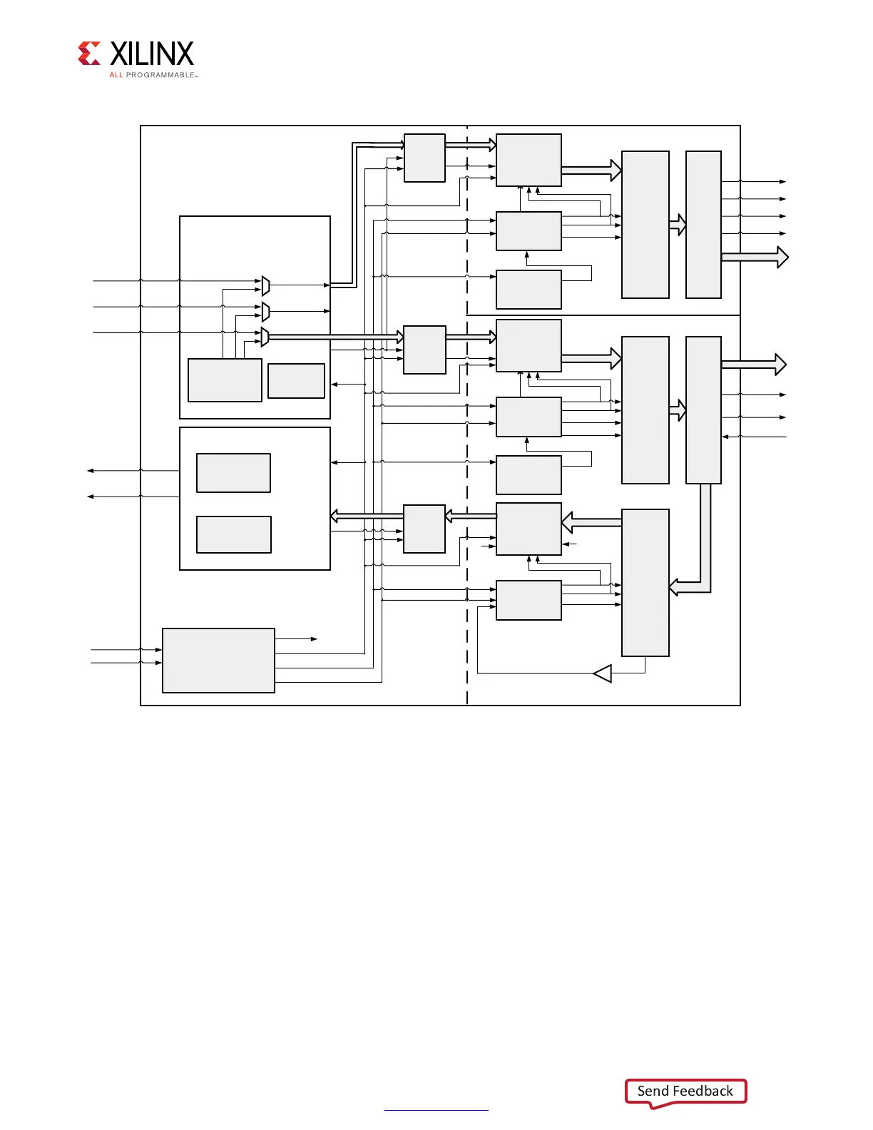
X-Ref Target - Figure 3-48
Figure 3-48: High-Level PHY Block Diagram of the RLDRAM II/RLDRAM 3 Interface Solution
5'?C??
)NITIALIZATION
ANDCALIBRATION
COMMAND
SEQUENCER
RLD?PHY?WRITE?TOP
MC?COMMANDS
MC?ADDRESSBA
MC?WRDATADM
STATE
!DDRESS#ONTROLBANK
/54?&)&/S
0(!3%2?
/54?0(9
/,/')#
/3%2$%3
2EADLEVELING
STAGE
PHY?READ?TOP
#LOCKAND2ESET
'ENERATIONBLOCK
3YNC?IN
0HY?CLK
-%-?2%&#,+
&2%1?2%&#,+
COMMANDS
ADDRESSBA
WRDATADM
STATE
-%-2%&#,+
&2%12%&#,+
)/"
0(!3%2?).
-%-2%&#,+
&2%12%&#,+
3TAGECALIBRATION
ANDDATAVALID
SIGNALGENERATION
USER?RD?VALID
USER?RD?DATA
7RITE2EADDATABANK
3YSTEM#LOCK
3YSTEM2ESET
2,$2!-))2,$2!-)NTERFACE
&
2%1
""
0(!3%2%&#,+
"5&-2S
0(9?#.42,?
",/#+
CTL BUS
-%-2%&#,+
2
#,+
2%
3
%4
/54?&)&/S
0(!3%2?
/54?0(9
/#,+$)6
/#,+
-%-2%&#,+
&2%12%&#,+
0(9?#.42,
",/#+
/,/')# RST
CTL BUS
-%-2%&#,+
2#
,
+
2%
3
%4
/#,+$%,!9%$
/#,+$)6
/#,+
/,/')# RST
),/')#
)$%,!9
)3%2$%3
).?&)&/S
)#,+$)6
),/')# RST
7#,
+
2%
3
%4
7#,+
7#,+
2#,+
)#,+
#,+
0/34?&)&/
72%.
2$%.
2$%.
#,+
1
$
1$
02%?&)&/
72%.
#,+
$
1
72%.
$
2$%.
2$%
.
72%.
#,+
$
1
!$
$2
#
-$
02%?&)&/
72%.
$
RLD?CKCK
RLD?CS?N
RLD?ABA
RLD?WE?N
RLD?REF?N
RLD?DQ
RLD?DM
RLD?QKQK
RLD?DKDK
/,/')#
/3%2$%3
)/"
7RITE#ALIBRATION
.OTE"5&-2ISONLYUSEDIN2,$2!-))
 Loading...


