SIP User's Manual 20 Document #: LTRT-68806
Mediant 2000 & TP-1610 & TP-260/UNI
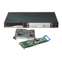
Table 2-1: Mediant 2000 Front View Component Descriptions
Item # Label Component Description
1 FAULT
Dual AC Power LED
2 --
cPCI blade locking screws
3 --
cPCI latches
4 --
TP-1610 cPCI blade, 16-trunk configuration
5 --
Status LED Indicators
6 T1/E1 STATUS
E1/T1 Trunk Status LED Indicators
7 ETH
Ethernet LED Indicators
8
-- Reset button
9
-- cPCI LED Indicators
10
-- Power and Fan LEDs
11
-- An available cPCI slot for an optional third-party CPU blade
2.1.1 Mediant 2000 Chassis
The Mediant 2000 chassis is an industrial platform that is 19” wide, 1U high and 12” deep.
The chassis houses the TP-1610 blade in its front cage in slot #1 (the lower slot), and the
TP-1610 RTM in its rear cage in slot #1 (the lower slot).
The Mediant 2000 chassis’ Slot # 2 in the front and rear cages can optionally be used by
customers for a CPU blade.
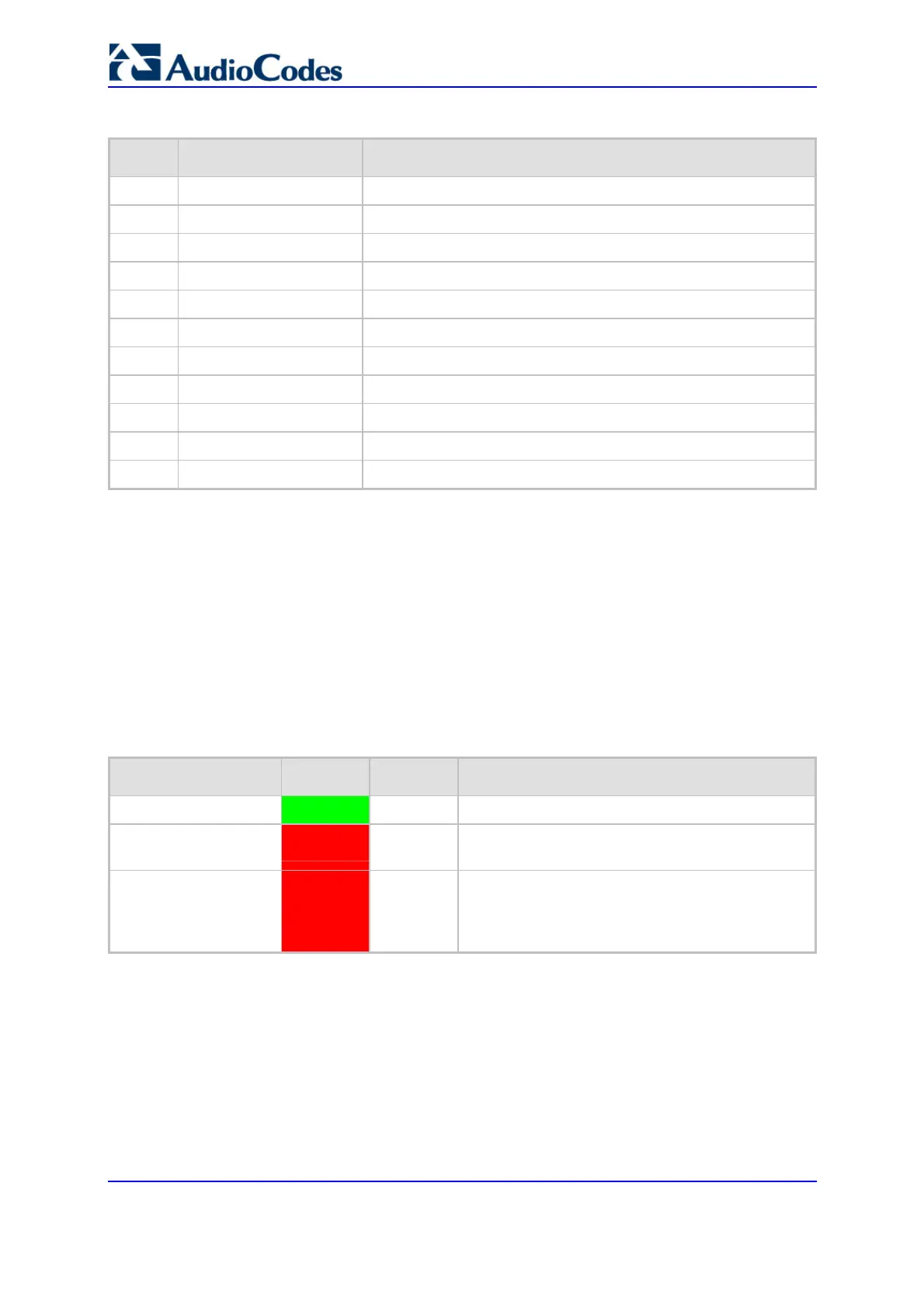
The table below describes the chassis’ LED indicators.
Table 2-2: Chassis LEDs Description
Location Color Color Description
Right side of front panel
Green
On The power is on.
Right side of front panel
Red
On
At least one of the internal fans has significantly
reduced its speed or has stopped (i.e., fan failure).
Left side of front panel
Red
On
One of the two AC redundant power supplies is
faulty or disconnected from the AC/mains outlet
(i.e., power supply failure). This LED is only
relevant for the dual AC power supply.
2.1.2 Power Supply
The Mediant 2000 power supply is available in three configuration options:
Single universal 100-240 VAC, 1 A max, 50-60 Hz
Dual-redundant 100-240 VAC, 1.5 A max, 50-60 Hz
-48 VDC power supply suitable for field wiring applications
 Loading...