SIP User's Manual 22 Document #: LTRT-68806
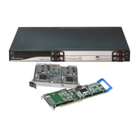
Mediant 2000 & TP-1610 & TP-260/UNI
Table 2-3: Front and Upper View of the TP-1610 cPCI Blade Component Descriptions
Item # Label Component Description
1
-- Status LEDs
2 ETH
Ethernet LEDs
3 --
Reset button
4 --
cPCI LEDs
5 --
cPCI Latch
6 T1 / E1 STATUS
T1/E1 Trunk Status LEDs (for each of the 1 - 8 trunks)
7 T1 / E1 STATUS
T1/E1 Trunk Status LEDs (for each of the 9 - 16 trunks)
2.2.1 TP-1610 Front Panel LEDs
The functionality of the TP-1610 front panel LEDs is described in the following tables.
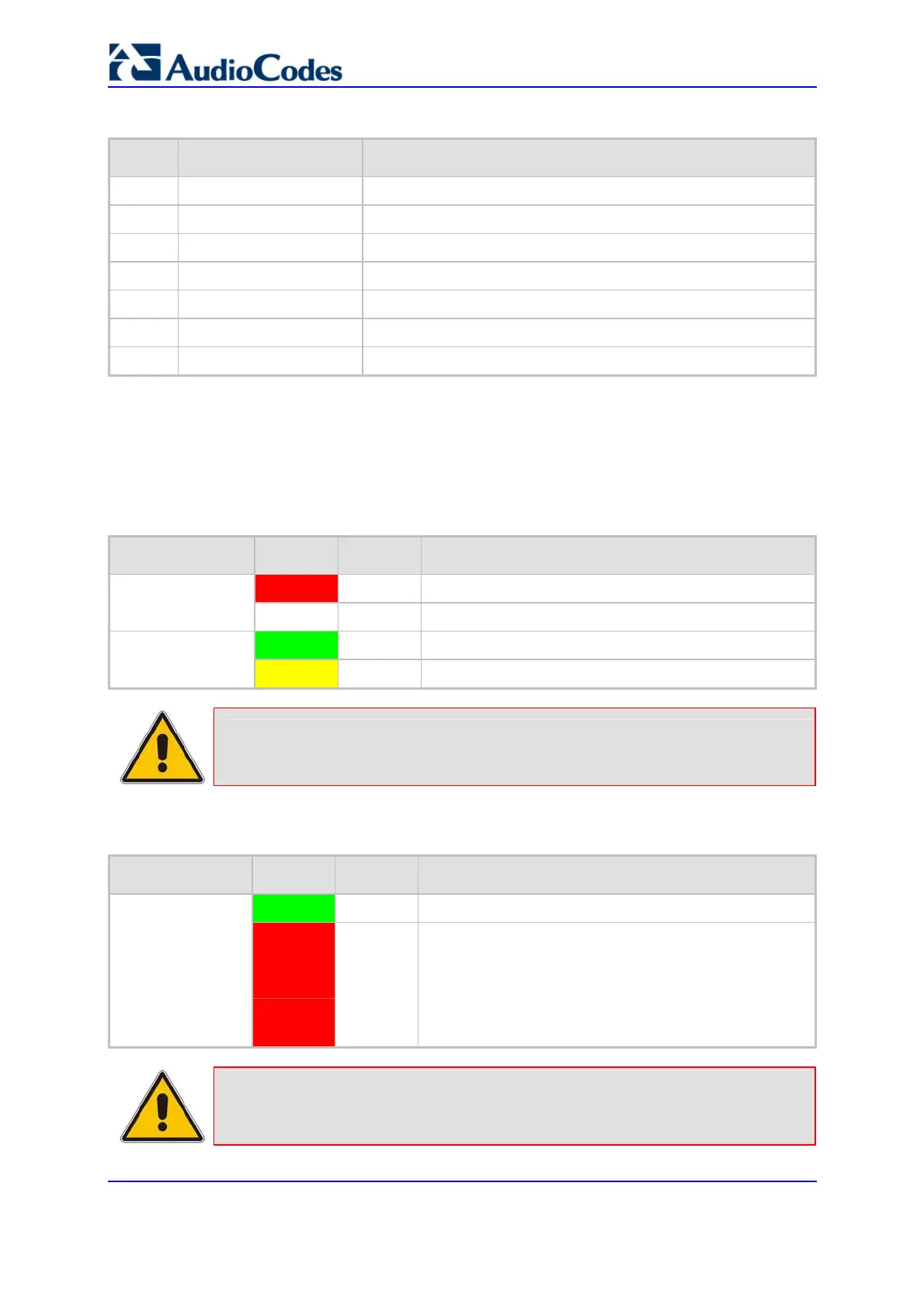
Table 2-4: Status LEDs Description
Label Color Status Description
Red
On gateway failure (fatal error)
FAIL
--
Off Normal functioning
Green
On gateway initialization sequence terminated OK
ACT
Yellow
On N/A
Note: During correct operation, the ACT LED is lit green and the FAIL LED is off.
Changing of the FAIL LED to red indicates a failure.
Table 2-5: E1/T1 Trunk Status LEDs Description
Label Color Status Description
Green
On Trunk is synchronized (normal operation)
T1/E1 Status 1 to 8
and
T1/E1 Status 9 to
16
Red
On
Loss due to any of the following 4 signals:
LOS Loss of Signal
LOF (Loss of Frame)
AIS (Alarm Indication Signal -- 'Blue alarm')
RAI (Remote Alarm Indication -- 'Yellow alarm')
Note: On the front panel, 16 LEDs are provided for 16-span units and 8 LEDs are
provided for 1-span, 2-span, 4-span, and 8-span units. In the case of 1-span,
2-span and 4-span units, the extra LEDs are unused.
 Loading...