Version 5.2 261 September 2007
SIP User's Manual 5. Web-based Management
5.14.1 Accessing the Home Page
¾ To access the Home page, take this step:
Open the Home page by clicking the Home icon; the Home page is displayed.
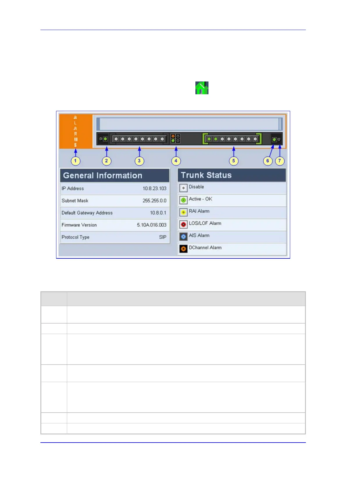
Figure 5-68: Home Page
The table below describes the areas of the graphic display of the gateway chassis.
Table 5-57: Description of the Areas of the Home Page
Item# Description
1
ALARMS area for viewing the Active Alarms table. For a detailed description, refer to
'Viewing the Active Alarms Table' on page 263.
2
Blade status LEDs.
3
T1/E1 Trunk Status LEDs (for each of the 1 - 8 trunks). You can switch modules (refer to
'Switching Between Mediant 2000 Modules' on page 262), view port settings (refer to
'Viewing Trunk Settings' on page 264), and assign a name to a port (refer to 'Assigning a
Name to a Port' on page 266).
4
Ethernet LEDs (green is active; grey is inactive). For a detailed description, refer to 'Viewing
Ethernet Port Information' on page 262.
5
T1/E1 Trunk Status LEDs (for each of the 9 - 16 trunks).You can switch modules (refer to
'Switching Between Mediant 2000 Modules' on page 262), view port settings (refer to
'Viewing Trunk Settings' on page 264), and assign a name to a port (refer to 'Assigning a
Name to a Port' on page 266).
6
Power LED.
7
Swap Ready LED.
 Loading...